- Home/
- GATE MECHANICAL/
- GATE ME/
- Article
Shear Force and Bending Moment Diagrams: SFD and BMD Notes
By BYJU'S Exam Prep
Updated on: September 25th, 2023

Shear Force and Bending Moment Diagrams PDF(Download)
Table of content
What are Shear Force and Bending Moments?
Shear force and bending moment are two fundamental concepts in structural engineering that describe the internal forces and moments within a structure. It can be described as follows:
- Shear force is the force that acts parallel to the cross-sectional area of a structure, perpendicular to the axis of the beam or member.
- Shear force is the force that tends to cause the upper and lower parts of the structure to slide past each other.
- Shear forces can be caused by external loads, such as the weight of the structure or the forces of wind or seismic activity.
- The bending moment is the moment that is created when an external force is applied to a structure, causing it to bend or flex.
- The bending moment is calculated by multiplying the force by the distance between the point of application and the point of support.
- Shear force and bending moment play a critical role in determining the strength and stability of a structure. Engineers use these concepts to design structures that can withstand the loads and forces that they are likely to encounter over their lifetimes.
Shear Force and Bending Moment Diagram
The bending moment and shear force diagram are the diagrams that represent the variation of the bending moment and shear force, respectively, across the length of the structural member. This will depend on the type of structural member, load, support reactions, etc. So, the idea about different structural members like beams and various support conditions is necessary to understand SFD and BMD.
Types of Rigid Supports
Supports are the structural component that provides rigidity in a few directions and flexibility in a few directions. Here some characteristics of the few supports are explained below:
- Simple Supports
- Roller Support
- Hinge Support (or) Pin Support
- Fixed Supports
- Clamped Supports (or) Built-in Supports
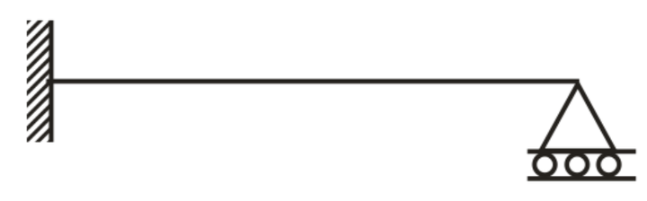
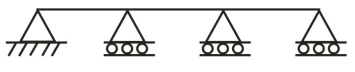
(a) Roller Support – It will resist vertical forces only and does not provide rigidity for the horizontal forces and moments.
(b) Hinge support or pin connection – It will resist horizontal and vertical forces only. It does not provide rigidity against rotation.
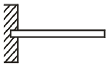
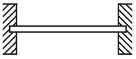
(c) Fixed support or built-in end – It will resist horizontal force, vertical force, and bending moment acting over it.
Note: The distance between two supports is known as “span”.
Types of Beams
A Beam is defined as a structural member subjected to transverse shear loads during its functionality. Due to those transverse shear loads, beams are subjected to variable shear force and variable bending moment.
The classification of beams depends on several factors like the determinacy of the beam, use of beams, etc. Here the types of beams based on their determinacy are given:
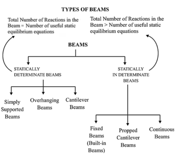
Statically Determinate Beam
A beam is statically determinate if all its reaction components can be calculated by applying three conditions of static equilibrium.
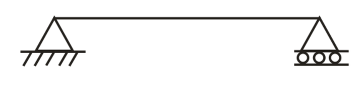
(1) Simply supported beam: A beam with two simple supports
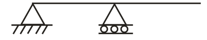
(2) Overhanging beam
(3) Cantilever beam: Beam fixed at one end and free at other
Statically Indeterminate Beam
When the number of unknown reaction components exceeds the static conditions of equilibrium, the beam is said to be statically indeterminate.
(1) Fixed Beams
(2) Propped Cantilever Beams
(3) Continuous beam: A beam is said to be a continuous beam if it has more than two supports
Types of Load
The following are the important types of load acting on a beam,
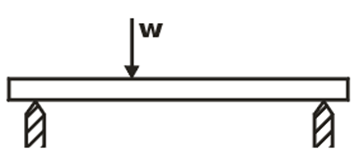
- Concentrated or point load,
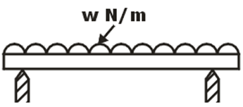
- Uniformly distributed load, and
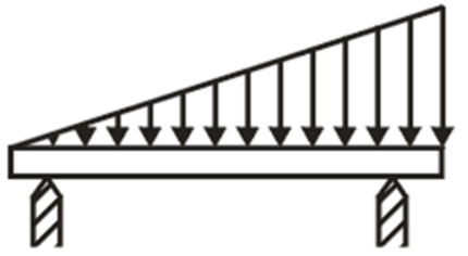
- Uniformly varying load.
(i) Concentrated or Point Load: if external load act at a point
(ii) Uniformly Distributed Load: load spread over a beam, rate of loading w is uniform along the length
(iii) Uniformly Varying Load: load spread over a beam, rate of loading varies from point to point along the beam
Sign Conventions for Shear Force and Bending Moment
Shear force at a beam cross-section is the sum of all the vertical forces either at the left or right sides of that cross-section. And the bending moment at a beam cross-section is the sum of all the moments either at the left or right sides of that cross-section.
A proper sign convention should be used to draw SFD and BMD. and it can be explained as below:
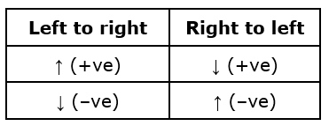
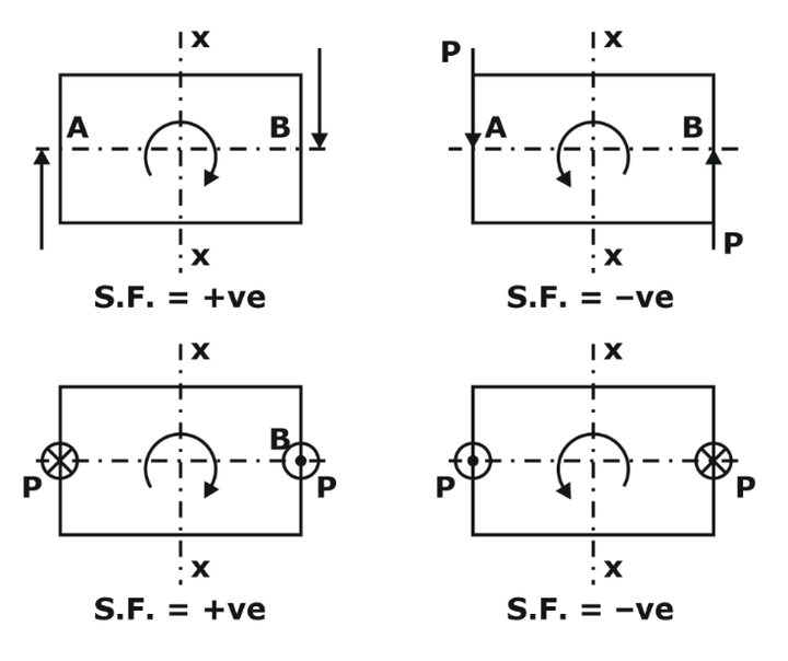
Sign Convention for Shear Force
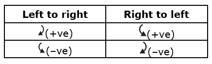
If moving from left to right, take all upward forces as positive and downward as negative.
Or if the shear force tries to rotate the element clockwise, then it is taken as positive & if the shear force tries to rotate the element anticlockwise, it is taken as negative.
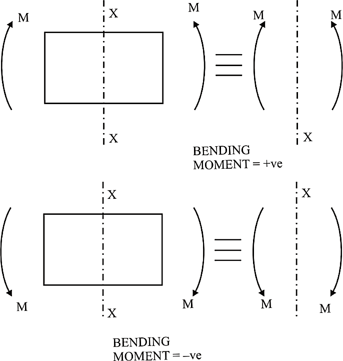
Sign Convention for Bending moment
If moving from left to right, take the clockwise moment as positive and anticlockwise as negative.
Or if forces are forming a sagging moment, it is taken as positive, and if forces are forming a hogging moment, it is taken as negative.
Important Points for Drawing Shear Force and Bending Moment Diagrams
Drawing of SFD and BMD is important for the proper analysis of the structural member. It will be carried out based on the external load acting over it and the type of support for the particular beam. Here are a few points that should be considered while drawing the bending moment and shear the diagram.
(i) Consider the left or the right portion of the section.
(ii) The positive values of shear force and bending moments are plotted above, and negative values are below the baseline.
(iii) The shear force diagram will increase or decrease suddenly i.e., by a vertical straight line at a section with a vertical point load.
(iv) The shear force between two vertical loads will be constant; hence, the shear force diagram between two vertical loads will be horizontal.
(v) The bending moment at the two supports of a simply supported beam and at the free end of a cantilever will be zero.
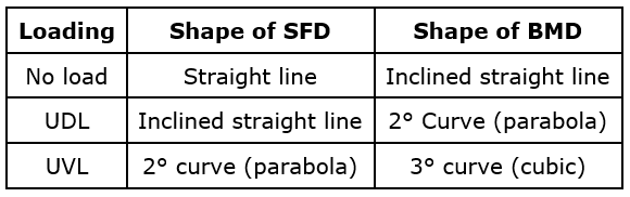
Relations Between Load, Shear Force and Bending Moment
Shear force, Bending moment, and external load acting over the beam can be interrelated. The relation can be derived based on the net force acting over the section. It can be explained below:
A beam carries a uniformly distributed load of w per unit length. Consider the equilibrium of the portion of the beam between sections 1-1 and 2-2. This portion is at a distance of x from left support and is of length dx.
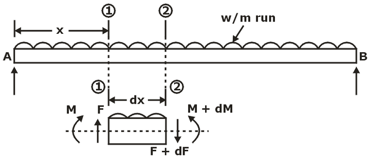
F = Shear force at section 1-1
F + dF = Shear force at section 2-2,
M = Bending moment at section 1-1,
M + dM = Bending moment at section 2-2.
The forces and moments acting on the length ‘dx’ of the beam are:
- The force F acting vertically up at sections 1-1
- The force F + dF acts vertically downwards at sections 2-2.
- The load w × dx acting downwards
- The moments M and (M + dM) act at section 1-1 and section 2-2, respectively.
The portion of the beam of length dx is in equilibrium. Hence resolving the forces acting on this part vertically, we get
–dF = w.dx
dF/dx = -w
The above equation shows that the shear force change rate equals the loading rate.
Taking the moments of the forces and couples about the sections 2-2, we get
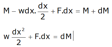
Neglecting the higher powers of small quantities, we get
F.dx = dM
F = dM/dx
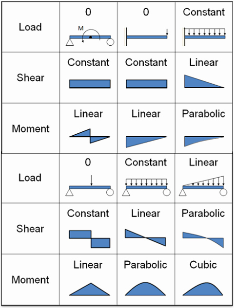
The above equation shows that the bending moment change rate equals the shear force at the section. Below are a few examples of the load, shear force, and bending moment for different beam support conditions.