
Bending Moment – Formula, Diagram with Examples
By BYJU'S Exam Prep
Updated on: September 25th, 2023

In the strength of material application of load, force and stress cause the deflection in the structural member. This deflection is can be positive or negative. Generally, it is called bending, and the effect generated by the applied force is known as the bending moment. The bending moment also depends on the direction of the application of stress.
In this article, we are about to learn what a bending moment is and what type of bending moment occurs in the standard case of structural cross-section or loading conditions. These standard cases are based on the structure member support type or direction of loading.
Download Formulas for GATE Civil Engineering – Solid Mechanics
Table of content
Bending Moment Formula
The bending moment is the algebraic sum of the applied load to the given distance from the reference point. Bending moments will also be caused due to the sum of applied moments from the reference point. The bending moment is an important part of the GATE CE syllabus. Generally, a moment that will cause the bending in a structural member is known as a bending moment.
The strength of the material, structural analysis, reinforced cement concrete, and steel analysis all use the bending moment equation. In the bending moment equation, the bending moment has a relationship with:
M/I = f/y = E/R
Where;
- M = Bending moment, I = Moment of Inertia
- f = Bending Stress
- y = Distance of outer fiber from C.G
- E = Modulus of Elasticity
- R = Radius of Curvature
Download Formulas for GATE Civil Engineering – Fluid Mechanics
Bending Moment Diagram
The bending moment calculation is done for different support conditions such as simply supported, cantilever support, propped cantilever support, overhanging support, or continuous support with different load combinations such as point load, uniformly load, gradually varied load, or direct moment. The bending moment diagram of various objects is asked in the GATE exam; hence it is advised to study this section with utmost care.
The basic principle of determination of bending moment is the applied load or force multiplied by the distance from the reference point on the span of the structural member.
Download Formulas for GATE Civil Engineering – Environmental Engineering
Bending Moment Examples
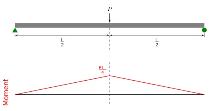
A simply supported beam has a point load at mid-span. The bending moment can be determined as a central point load of P divided by the support as 0.5P; this value is known as the support reaction. We know the length of the span is L. We know that the value of the bending moment is zero as pinned support or simply support. We have got the maximum bending moment at the center of the span. Hence this way, the support reaction is multiplied by the half length of the span. This way, I got the bending moment at the center as 0.25PL. As per the diagram, we can see this-
Standard Cases of Bending Moment
We know the bending moment can be derived from the applied load and given distance. Various MCQ-based questions are seen on this in the GATE question paper. Generally, some cases are derived for standardization, these standard cases are created as reference cases, and we can design the structural member by just rearranging the load condition and span dimensions. Some of these are
|
S.NO. |
Standard Cases |
Maximum Bending Moment |
|
1. |
If a simply supported beam carrying a central point load as W with span L. |
WL/4 |
|
2. |
If a simply supported beam carrying a uniformly distributed load as W (N/m) with span L. |
WL/4xL/2 |
|
3. |
If a simply supported beam carrying a uniformly distributed load as W (KN) with span L. |
WL/8 |
|
4. |
If an eccentric point load at a beam at “a” distance from left support and “b” distance from right support when the total length of the span is L. |
Wab/L |
|
5. |
If a simply supported beam with L span carries two point load L/3 distance away from both supports. |
WL/3 |
|
6. |
If a simply supported beam carrying a moment M at “a” distance from left-hand support or “b” distance away from right-hand support with span L of member |
Positive maximum moment = +Mb/L Negative maximum moment = -Mb/L |
|
7. |
A simply supported beam carrying U.V.L at zero on left support and W on right support with span L. |
WL/6xL/2 |
|
8. |
A fixed beam that carries a central point load as W. |
At center = WL/8 At support = WL/8 |
|
9. |
A fixed beam that carries a U.D.L N/m at span L. |
At center = WL/12xL/2 At support = WL/6xL/2 |
|
10. |
A fixed beam that carries U.V.L with intensity zero to W |
At zero load support = WL/15xL/2 At W load support = WL/10xL/2 |
|
11. |
A cantilever beam carrying a point load on the free end with span L. |
WL |
Some Important Definitions
- At a point on a beam where shear force changes its sign, the point is known as the maximum bending moment position.
- At a point where the bending moment changes, the point of contra flexure is known.
- At a span where the shear force value is completely zero and the bending moment constant is called a pure bending span.
| Important Topics for Gate Exam | |
| Brittle Material | Capacitors in Parallel |
| Capacitors in Series | Carnot Cycle |
| Cement Test | Clamping Circuit |
| Clipping Circuit | CMOS Fabrication |
| CMOS Converter | Column Base |


