
- Home/
- GATE ELECTRONICS/
- GATE EC/
- Article
LC Oscillators
By BYJU'S Exam Prep
Updated on: September 25th, 2023

For generating high-frequency signals, LC Oscillator is preferred. At higher frequencies, better results are obtained with LC-tuned oscillators. The transistors (BJTs and FETs) used in the LC oscillators are used in the frequency range of 100 kHz to 100 GHz.
The Quality factor of LC oscillator circuits is much higher than that of RC oscillators. It is difficult to tune the LC oscillators over a wide range of frequencies. In this article, get the LC Oscillator definition, Principle, Type, and working of Hartley and Colpitts oscillator.
Table of content
What is LC Oscillator?
LC oscillators generate very high-frequency sine waves by using a transistor as an amplifier, a tank circuit as a frequency-determining device, and a feedback circuit consisting of resistors.
LC Oscillator Definition
LC oscillator is also known as sinusoidal oscillators or Harmonic oscillators. LC oscillators can be designed using OP-AMP and Transistors. OP AMP-related LC oscillators provide much more frequency stability than Transistor’s LC oscillators. LC oscillators are preferred at higher frequencies because of their high-Quality factor and a wider range of frequencies.
Principle of LC Oscillators
A tank circuit, shown below, is used in the LC oscillator that contains a capacitor C and an inductor L. When a voltage is applied to the LC circuit, the capacitor gets charged, and when the supply voltage is removed, the stored energy from the capacitor gets discharged to the inductor.
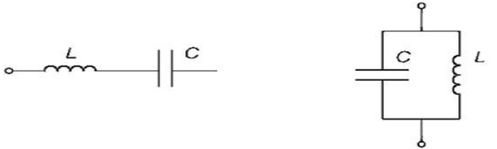
The inductor uses the released energy from the capacitor to form a magnetic field around it. This magnetic field induces a voltage and starts charging the capacitor with opposite polarity. This cycle between the inductor and capacitor continues and results in oscillations.
The oscillation frequency is produced when the tank circuit is under resonance.
|XL|=|XC|
2πfοL = 1/ 2πfοC
fο = 1/2π√(LC)
Types of LC Oscillators
There exist numerous types of LC oscillators used according to the desired application. Based on the output frequency of oscillation to be used, LC oscillators can be classified as:
- Colpitts oscillators
- Hartley oscillators
- Clapp oscillators
- Tuned collector oscillators
- Tuned base oscillator
The commonly used configurations of LC oscillators are Hartley, Colpitts, and Clapp oscillators. Colpitts and Hartley’s oscillators use a parallel LC tank circuit.
Colpitts Oscillators
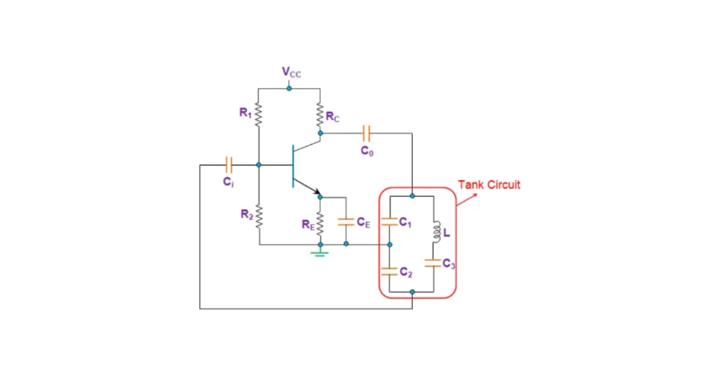
Colpitts Oscillators is one of the important LC Oscillators. In the Colpitts oscillator, a parallel LC circuit is connected between collector and base (for BJTs) or between Drain and Gate (for FETs) with a small, tuned circuit voltage applied to the emitter or Source as shown below:
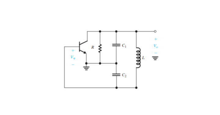
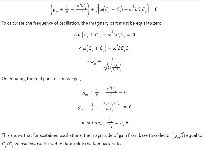
Feedback is achieved through the capacitive divider circuit used in the Colpitts oscillator. In this LC oscillator type, the ratio C1/C2 determines the feedback ratio and must be adjusted to ensure that oscillations will start. To determine the frequency of oscillation, replace the transistor with an equivalent AC model as shown below:
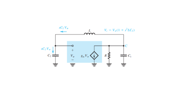
The resistor R includes the internal output impedance of the transistor r0. To simplify the analysis, r has been neglected, and all the interelectrode or internal capacitance of the transistor is assumed to be open.
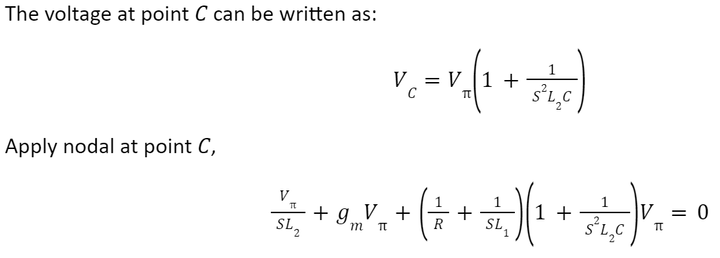
Apply nodal at point C,
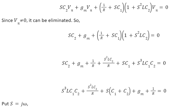
The Colpitts oscillator can also be designed using OP AMP as OP AMP provides greater frequency stability. Although the operation and the value of output or resonance frequency will remain the same for both. The circuit of the OP-AMP-based Colpitts oscillator is shown below:
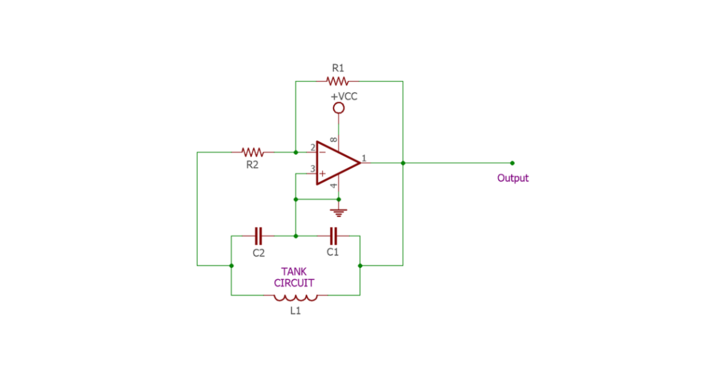
The frequency of oscillation will be the same and given by:
ωΟ = 1/[√(C1C2/(C1 + C2))]
Applications of Colpitts Oscillators
The Colpitts oscillator has a frequency range of 20 kHz to 2 MHz. High-frequency sinusoidal signals can be generated with the help of the Colpitts oscillator. This LC oscillator type is also used in Radio and Mobile communications systems for high-frequency signal generation.
Hartley Oscillators
In the Hartley oscillator, a parallel LC circuit is connected between collector and base (for BJTs) or between Drain and Gate (for FETs) with a small, tuned circuit voltage applied to the emitter or Source as done in Colpitts oscillators. The circuit of the Hartley oscillator is shown below:
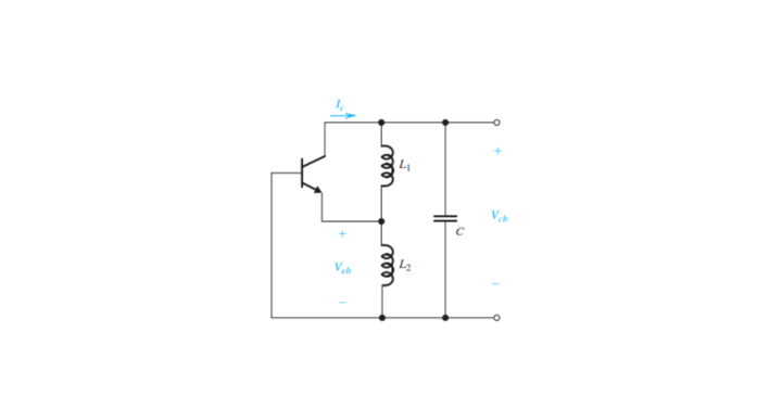
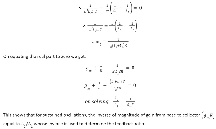
Feedback is achieved through the inductive divider circuit used in the Hartley oscillator. The ratio L1/L2 determines the feedback ratio and must be adjusted to ensure that oscillations will start. To determine the frequency of oscillation of this type of LC Oscillator, replace the transistor with an equivalent AC model as shown below:
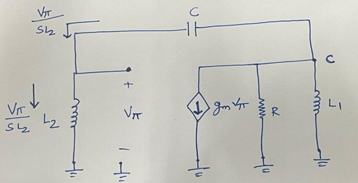
The resistor R includes the internal output impedance of the transistor r0. To simplify the analysis of this LC Oscillator, rΠ has been neglected, and all the interelectrode or internal capacitance of the transistor is assumed to be open.
To calculate the oscillation frequency, the imaginary part must be equal to zero.
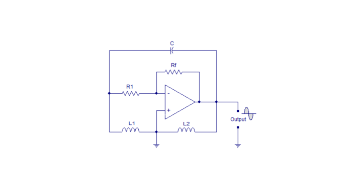
The Hartley oscillator can also be designed using OP AMP as OPAMP provides excellent frequency stability. Although the operation and the value of output or resonance frequency will remain the same for both. The circuit of the OP-AMP-based Hartley oscillator is shown below:
The frequency of oscillation for this type of LC Oscillator will be the same and given by:
ωΟ = 1/[1/√(L1L2/C)]
Applications of Hartley Oscillators
This LC oscillator is also used in Radio frequency and Mobile communications. The harmonic content at the output of the Hartley oscillator is dominant, so it cannot be used to generate a pure sine wave.
Clapp Oscillators
Clapp oscillator is an advanced version of Colpitts oscillator(LC oscillator type). If one additional capacitor is connected in series with an inductor in the Colpitts oscillator, it will form the Clapp oscillator. This additional capacitor provides frequency stability. The circuit of the Clapp oscillator is shown below:
The working of the Clapp oscillator is similar to that of the Colpitts oscillator. Apart from including extra capacitors in this type of LC oscillator, all other components are similar to that of the Colpitts oscillator. The oscillation frequency can be calculated by replacing the transistor with its AC equivalent. The equation gives the frequency of oscillation:
ωΟ = 1/[√(LCeq)]
where, Ceq = 1/ [1/Ceq + 1/Ceq + 1/Ceq]
Due to this extra capacitor C3, the Clapp oscillator is preferred over Colpitts because the frequency can be varied only by changing the value of capacitor C3; hence it will not affect the feedback ratio C1/C2. The capacitor C3 is kept smaller than both C1 and C2, so the frequency of oscillation can be approximated as follows:
ωΟ = 1/[√(LC3)]
Applications of Clapp Oscillators
This type of LC oscillator is used to construct a variable frequency oscillator as the frequency of the Clapp oscillator can be varied with the help of extra capacitor C3 without affecting the feedback ratio. Clapp oscillators are also used in tuned-receiver circuits.
Advantages and Disadvantages of LC Oscillator
There are various advantages of the LC Oscillator, which are provided below:
- At high frequencies, LC oscillators are really stable.
- Produces less noise than the other oscillators.
- The Q-factor of the LC oscillators is also high.
Despite various advantages, there are a few disadvantages of the LC Oscillators:
- The components of the LC Oscillator get affected because of the temperature variation.
- Variable operating frequency is also an issue with the LC Oscillators.
- Not very apt for functioning at low frequencies.


