
- Home/
- GATE ELECTRONICS/
- GATE EC/
- Article
Dynamic Resistance
By BYJU'S Exam Prep
Updated on: September 25th, 2023

Dynamic Resistance is the resistance a device offers when connected to an AC supply. Resistance of any device or material is its property to resist the flow of charges through it. Since the voltage keeps varying in an AC supply, the resistance is given by the ratio of a small change in voltage to a small change in the current value through it.
In this article, we will discuss the dynamic resistance of a diode device, a two-terminal semiconductor device. We will also talk about the characteristics of diodes and define dynamic resistance in them for different biasing conditions.
Download Formulas for GATE Electronics & Communication Engineering – Analog Circuits
Table of content
Define Dynamic Resistance
Dynamic resistance is defined as the resistance offered by the diode semiconductor device when an AC supply biases it. A basic connection with an AC supply to the diode is shown in the below figure.
It is given as the voltage change ratio to change in current across the diode. It is mathematically given as.
RAC = ΔV / ΔI
Where ΔV is the small change in voltage and ΔI is the change in current.
Resistance in a Diode
Diode resistance can be defined as the effective opposition provided by the diode when forward current flows through it. Therefore, diode resistance can be defined as the effective resistance a diode offers when biased with a supply. A diode when forward biased can have two types of resistance i.e., Static resitance and dynamic resistance.
Dynamic Resistance PDF
A diode’s forward and reverse resistances can be determined by its forward and reverse bias characteristics. No device, however, can be considered ideal. Therefore, practically speaking, every diode will offer a small resistance when forward biased and a significant resistance in reverse bias.
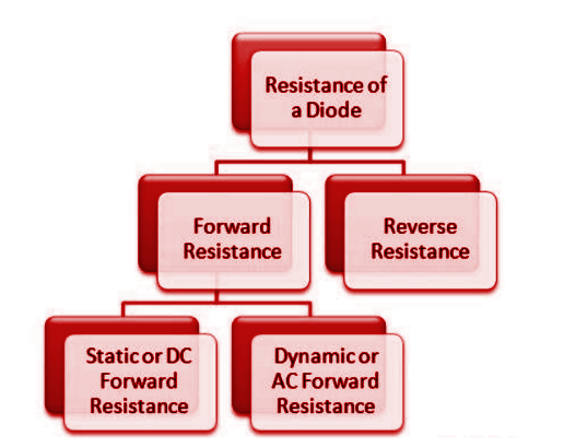
The above flow chart shows the different resistances an idea diode offers.
Download Formulas for GATE Electronics & Communication Engineering – Signals Systems
Dynamic Resistance in Forward Bias
Dynamic resistance can be calculated from the p-n junction diode’s V-I curve. It is defined as the ratio of a change in voltage to a change in current. The V-I curve of the p-n junction diode is given below.
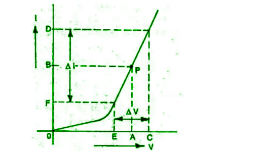
Dynamic Resistance in Forward Bias Formula
Mathematically the dynamic forward resistance is given as-
Rdf=(ΔV/ΔI) = ηVT/ I
Where VT is the thermal voltage and is given by Einstein’s equation equal to kT/q, where k is Boltzmann’s constant (k=8.85 x 10⁻¹² F/m)
Dynamic Resistance in Reverse Bias
A reverse bias increases p-n diode depletion layer width, which offers higher resistance to the flow of charge carriers. The reverse resistance of p-n diodes is in the Mega Ohm range. The reverse resistance is very large compared to the forward resistance of the diode.
Dynamic Resistance in Reverse Bias Formula
Mathematically the reverse dynamic resistance is given as-
Rdr = (ΔVr/ ΔIr)
Download Formulas for GATE Electronics & Communication Engineering – Digital Circuits


