
- Home/
- GATE MECHANICAL/
- GATE ME/
- Article
Slider Crank Mechanism: Theory and Applications
By BYJU'S Exam Prep
Updated on: September 25th, 2023

The slider crank mechanism is a typical mechanical linkage that changes rotational motion into linear motion or the other way around. It is widely used in various applications, including internal combustion engines, pumps and compressors, presses, robotics, toy cars, and human-powered vehicles.
Slider Crank Mechanism PDF
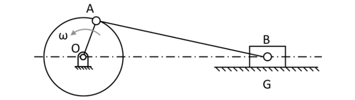
The slider-crank mechanism consists of three main components: a crank, a connecting rod, and a slider. The crank is a rotating shaft driven by a motor or other power source. The connecting rod is a linear link that connects the crank to the slider. The slider is a sliding element that moves back and forth along a straight line. As the crank rotates, it drives the connecting rod and slider through a series of pivot points, causing the slider to move back and forth. The speed and distance of the slider’s movement can be controlled by adjusting the connecting rod’s length, the crank’s speed, or the pivot points’ position.
Download Formulas for GATE Mechanical Engineering – TOM & Vibrations
Table of content
What is the Slider Crank Mechanism?
The slider-crank mechanism consists of three main components: a crank, a connecting rod, and a slider. The crank is a rotating shaft driven by a motor or other power source. It is typically connected to the connecting rod at one end and rotates around a fixed axis. The connecting rod is a linear link that connects the crank to the slider. It is typically made of strong and flexible material, such as metal or plastic and important topic of the GATE ME syllabus.. The slider is a sliding element that moves back and forth along a straight line. It is connected to the connecting rod at one end and can perform various tasks, such as pressing, pushing, pulling, or lifting.
As the crank rotates, it drives the connecting rod and slider through a series of pivot points, causing the slider to move back and forth. The speed and distance of the slider’s movement can be controlled by adjusting the connecting rod’s length, the crank’s speed, or the pivot points’ position. The slider-crank mechanism is widely used in various applications, including internal combustion engines, pumps and compressors, presses, robotics, toy cars, and human-powered vehicles. It is a simple and reliable way to convert rotational motion into linear or vice versa.
Slider Crank Mechanism Theory
The theory of the slider-crank mechanism is based on the principles of kinematics, which is the study of motion without considering the forces that cause it. In a slider-crank mechanism, the motion of the crank and connecting rod is described by kinematic equations that relate the two components’ position, velocity, and acceleration. These equations are typically derived using principles of geometry and trigonometry and can be used to predict the motion of the slider-crank mechanism under different conditions.
The slider’s position can be described using the crank angle, which is the angle between the crank and a reference line. The velocity and acceleration of the slider can be calculated by differentiating the position equation concerning time. In addition to the kinematic equations, the slider-crank mechanism can also be analyzed using dynamics principles, which study the motion and the forces that cause it. This includes the analysis of the forces acting on the components of the mechanism and the torque required to drive the crank. The slider-crank mechanism theory is important for the GATE exam and designing and controlling systems that use this linkage, such as internal combustion engines, pumps and compressors, presses, robotics, toy cars, and human-powered vehicles.
Download Formulas for GATE Mechanical Engineering – Manufacturing Engineering and Materials
Function of a Slider Crank Mechanism
The slider-crank mechanism consists of a crank, a rotating shaft, and a connecting rod, a linear link that connects the crank to a sliding element called a slider. The crank is typically driven by a motor or other power source, which causes it to rotate around a fixed axis. As the crank rotates, it drives the connecting rod and slider through a series of pivot points, causing the slider to move back and forth in a straight line.
The movement of the slider can be used to perform various tasks, such as pressing, pushing, pulling, or lifting. The speed and distance of the slider’s movement can be controlled by adjusting the connecting rod’s length, the crank’s speed, or the pivot points’ position. The slider-crank mechanism is widely used in various applications, including internal combustion engines, pumps and compressors, presses, robotics, toy cars, and human-powered vehicles. It is a simple and reliable way to convert rotational motion into linear or vice versa.
Applications of Slider Crank Mechanism
The slider-crank system is a typical mechanical linkage that changes rotational motion into linear motion or the other way around. It is widely employed in many different applications, such as:
-
Internal combustion engines: The slider-crank mechanism is used in internal combustion engines to convert the reciprocating motion of the pistons into the rotational motion of the crankshaft.
-
Pumps and compressors: The slider-crank mechanism is used in pumps and compressors to transfer fluid or gas from one location to another.
-
Presses: The slider-crank mechanism is used in mechanical presses to apply force to a workpiece, such as in stamping or forging operations.
-
Robotics: The slider-crank mechanism is used in robotics to provide linear motion for tasks such as welding or assembly.
-
Toy cars: The slider-crank mechanism is used in toy cars to convert the rotational motion of the wheels into the linear motion of the car’s body.
-
Human-powered vehicles: The slider-crank mechanism is used in human-powered vehicles, such as bicycles and rowing machines, to convert the linear motion of the pedals or oars into the rotational motion of the wheels or propellers.
Download Formulas for GATE Mechanical Engineering – Strength of Materials
Advantages of Slider Crank Mechanism
There are several advantages to using a slider-crank mechanism which are important for GATE ME exam:
-
Simplicity: The slider-crank mechanism is a simple and reliable mechanical linkage that is easy to design and build. It consists of only three main components: a crank, a connecting rod, and a slider.
-
Versatility: The slider-crank mechanism can perform various tasks, including pressing, pushing, pulling, and lifting. It can also convert rotational motion into linear motion or vice versa.
-
Precision: The slider-crank mechanism can provide precise and repeatable motion, which is useful for tasks that require high levels of accuracy, such as assembly, welding, and painting.
-
Compactness: The slider-crank mechanism can be designed to be compact and lightweight, making it suitable for use in limited space.
-
Cost: The slider-crank mechanism is relatively inexpensive to design and build, especially when compared to more complex mechanical linkages.
-
Safety: The slider-crank mechanism can be designed to be safe for use around humans and can be equipped with sensors and other safety features to prevent accidents.
Disadvantages of Slider Crank Mechanism
There are also some disadvantages to using a slider-crank mechanism:
-
Limited range of motion: The range of motion of a slider-crank mechanism is limited by the lengths and orientations of the crank and connecting rod and the constraints imposed by the pivot points.
-
Sensitivity to external forces: The slider-crank mechanism can be sensitive to external forces, such as wind or vibrations, affecting its performance.
-
Complexity: The design and control of a slider-crank mechanism can be complex, especially for systems with many degrees of freedom.
-
Limited adaptability: The slider-crank mechanism is typically designed for specific tasks and may not easily adapt to new tasks or environments.
-
Wear and maintenance: The slider-crank mechanism can suffer from wear and tear and may require regular maintenance to keep it operating at its best.
Get complete information about the GATE exam pattern, cut-off, and all those related things on the BYJUS Exam Prep official youtube channel.


