
- Home/
- GATE MECHANICAL/
- GATE ME/
- Article
Design of Shafts
By BYJU'S Exam Prep
Updated on: September 25th, 2023

Before we go into the details of the design of shafts, let us first define what a shaft is. A shaft is a spinning machine element with a circular cross-section used to convey power from one part to another or from a power-producing machine to a power-absorbing machine. Shafts are an essential component of machinery. They support rotating components such as gears and pulleys and are supported by bearings in the stiff machine housing.
The shafts’ job is to transfer power from one rotating element to another supported or connected. As a result, they are subjected to torque from power transfer and bending moments from the reactions of the members they support. Axles, which likewise support rotating components but do not transmit power, are not to be confused with shafts. The design of shafts is a common task in machines. Although common, the amount of attention that goes into the design of shafts can be surprising. Let’s look at the Design of Shaft in further detail.
Download Formulas for GATE Mechanical Engineering – Machine Design
Table of content
Design of Shafts
Shafts are always circular in cross-section and can be solid or hollow. Straight, cranked, flexible, or articulated shafts are the different types. Straight shafts are the most prevalent type of power transmission shaft. Although constant diameter shafts would be simple to construct, such shafts are often built as stepped cylindrical bars; they have varied diameters along their length. The stepped shafts represent the varying degree of stress along the length of the shaft.
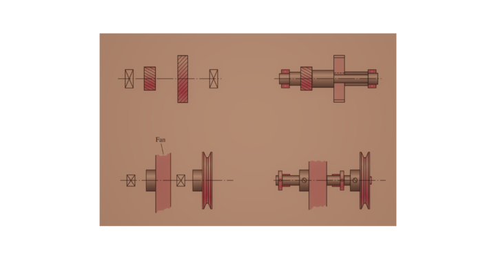
The figure shows the axial layout of the shaft and its various components.
Shafts are built for strength, stiffness, or a combination. In some circumstances, rigidity is also significant. For example, if the shaft is deflected, the position of a gear mounted on the shaft may change, and if this value exceeds some permissible limit, it may cause excessive dynamic loads and noise in the gears. The shafts can be designed based on two criteria:
- Strength
- Rigidity
Download Formulas for GATE Mechanical Engineering – Industrial Engineering
Design of Shafts Based on Strength
A strength-based design shaft ensures that stress at any point on the shaft does not exceed the material’s yield stress. When designing shafts based on strength, take into account the following scenarios:
- Shafts that are only subjected to a twisting moment or torque.
- Shafts that are solely susceptible to bending moments.
- Shafts are exposed to a combination of twisting and bending moments.
- Shafts are subjected to axial loads and torsional and bending loads.
Design of Shafts Based on Rigidity
The goal of the rigidity-based design of the shaft is to keep the shaft’s maximum deflection (due to bending) and maximum twist (due to torsion) within acceptable bounds. Rigidity is sometimes a factor to consider when designing shafts. The two sorts of rigidity that we’ll look at are as follows:
Torsional Rigidity
The torsional rigidity of a camshaft in an internal combustion engine is essential because it affects the valve timing. The maximum amount of twists allowed per meter length of such shafts is 0.25°. Deflections of 2.5 to 3 degrees per meter length can be utilized as a limitation value for line or transmission shafts. The most commonly utilized shaft deflection is 1 degree over a length equal to twenty times the diameter of the shaft.
☛ Learn more about Torsion of Shafts.
Lateral Rigidity
It’s crucial for transmission shafts and shafts moving at high speeds because even a slight lateral deflection can result in massive out-of-balance forces. Maintaining optimum bearing clearances and gear tooth alignment depend on lateral rigidity. The lateral deflection of a shaft can be calculated using the deflection formula found in Strength of Materials if the shaft has a uniform cross-section. However, if the shaft has a variable cross-section, the lateral deflection can be calculated using the fundamental equation for a beam’s elastic curve.
☛ Also, Know about the Modulus of Rigidity.
Download Formulas for GATE Mechanical Engineering-Engineering Mechanics
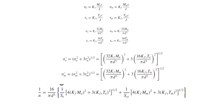
Design Stress
Various stresses are developed in the shaft for real-life uses, which shall be considered while designing the shafts. A few design stresses are provided in the figure shown below:
Design of Shaft for Flywheel
This is about the design of the shaft for a flywheel. The flywheel keeps the engine’s speed fluctuation to a minimum possible value. The maximum torque transferred is used to determine the diameter of the shaft for the flywheel. We know the maximum torque that can be transmitted.
Tmax = (π/16) * τ(d)3
where
- d = Diameter of the shaft
- τ= Allowable shear stress for the shaft’s material
For maximum torque transmission, the hub is designed as a hollow shaft. We know the maximum torque that can be transmitted.
Tmax = (π/16) * τ[(d4 – d14)/d]3
where
- d = Outer diameter of the hub
- d1 = The shaft’s diameter or the hub’s inner diameter.


