
- Home/
- GATE MECHANICAL/
- GATE ME/
- Article
Bolted, Riveted and Welded Joints Study Notes for GATE Mechanical Exam
By BYJU'S Exam Prep
Updated on: September 25th, 2023

Joints play a critical role in connecting structural components, and understanding their behaviour is essential for mechanical engineers involved in designing and analyzing various systems. This study notes delve into the principles, design considerations, and applications of bolted, riveted, and welded joints, equipping students and professionals with the knowledge to make informed decisions while selecting the most suitable joint type for different engineering scenarios.
In this study material, we explore the characteristics and advantages of bolted joints, which rely on threaded fasteners to hold components together. We cover topics such as bolt types, preload, and the effect of external forces on the integrity of bolted connections. Additionally, we investigate riveted joints, which were historically widely used in structural applications. Understanding the riveting process, types of rivets, and factors affecting joint strength enables a comprehensive grasp of their applications in modern engineering. Moreover, the study notes delve into welded joints, where metals are fused together to create robust connections. We examine different welding techniques, weld defects, and considerations for selecting appropriate welding methods in diverse mechanical engineering scenarios. Whether you are preparing for the GATE Mechanical Exam or seeking to enhance your knowledge in this field, these study notes will prove invaluable in mastering the complexities of bolted, riveted, and welded joints.
Table of content
What is Joint: Definition & its Properties
Joints: Joints are temporary and permanent in nature. Permanent joints are further categorised in welded joints and Riveted joints.
Advantages of riveted joints over welded joints:
- More reliable in applications subjected to vibrations and impact forces
- Riveted joints can be used for non-ferrous metals like aluminium alloy, copper, brass etc.
- Less damage to the connected parts when the joint is dismantled
Properties of Rivets
Given below are the important properties of rivets.
- The rivet should be sound, free from cracks, flaws, burrs, seams, pits and other defects
- The head of the rivet should be concentric with the axis of the shank
- The end of the rivet should be square with respect to the axis
Terminology of Riveted Joints:
- Pitch (p): Distance between the centre of one rivet to the centre of the adjacent rivet in the same row.
- Margin (m): distance between the edge of the plate to the centerline of the rivets in the nearest row.
- Transverse pitch (back pitch or row pitch): The distance between two consecutive rows of rivets in the same plate is termed transverse pitch.
- Diagonal pitch: The centre distance between one rivet and its adjacent rivet located in the adjacent row is called as diagonal pitch.
- Strength of riveted joint: The strength of the riveted joint is the force that the joint can carry without causing joint failure.
Shear Strength of Riveted Joint:
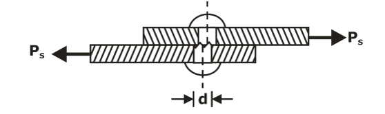
The shear strength of the riveted joint is:
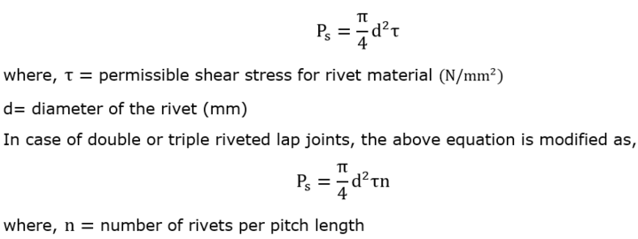
In case of double-strap single-riveted butt joint, the rivets are subjected to double shear as shown below:
Shear strength of double-riveted lap joint:
![]()
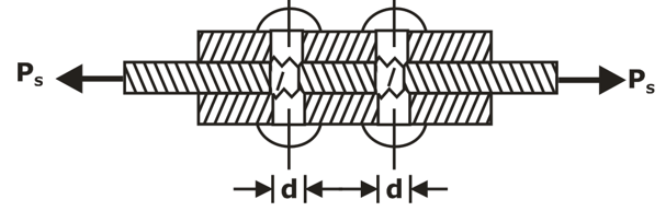
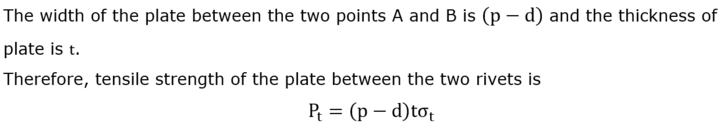
Tensile Strength of Plate Between Rivets:
Crushing Strength of Riveted Joint:
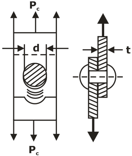
The failure occurs results if compressive stress between the shank of the rivet and the plate is more than the yield stress in compression.
The crushing strength is given by:
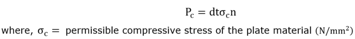
The efficiency of Riveted Joint
- It is the ratio of the strength of riveted joint to the strength of the unriveted solid plate.
- The strength of a solid plate having a width same as the pitch (p) and thickness (t), acted to tensile force, is given by:
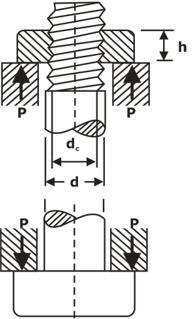
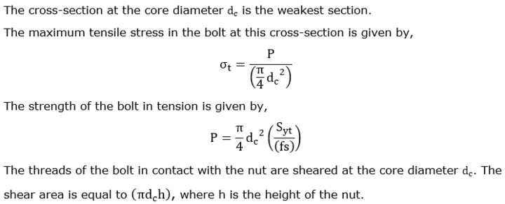
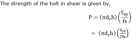
Bolted Joint analysis: A bolted joint subjected to tensile force P is shown in the figure:
Eccentrically loaded bolted joint in shear: An eccentrically loaded bolted connection is shown in the figure
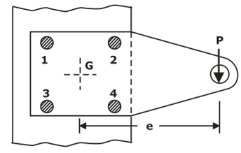
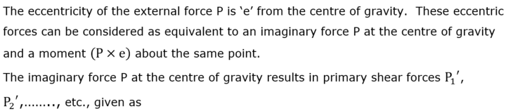
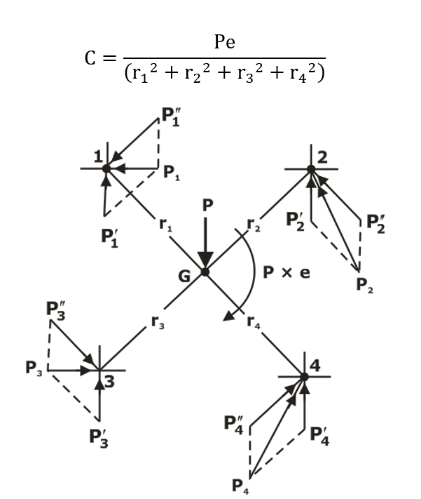
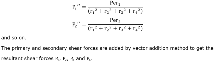
Eccentric load perpendicular to the axis of the bolt: A bracket, fixed to the steel structure by means of four bolts, is shown in the figure:
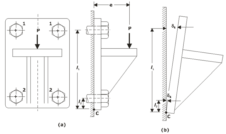
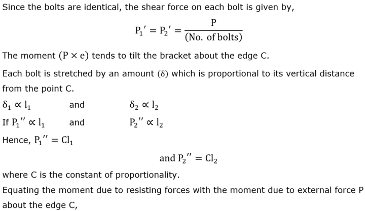
The bolt 1 is acted to maximum force i.e. farthest located bolt from the tilting edge C is subjected to maximum force.
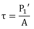
The direct shear stress of the bolt is:
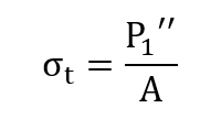
The tensile stress of the bolt is:
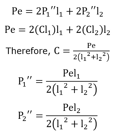
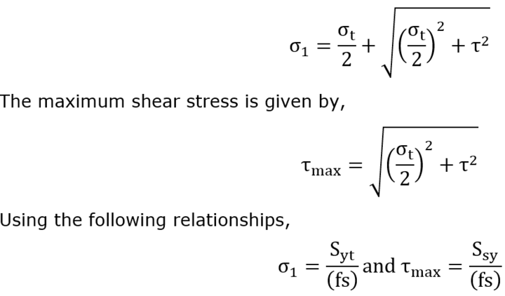
The maximum principal stress theory or maximum shear stress theory is used for the design of the bolts. Thus:
The maximum principal stress is given by:
Welded Joints: Welding is a joining process of metallic parts by heating to a suitable temperature with or without the application of pressure and with or without filler metal.
Stress-relieving of welded joints: One of the major disadvantages of welded joints is that it is subjected to residual stresses due to non-uniform heating of the parts being joined.
The following two methods can reduce the residual stresses:
- Preheating of the weld area to retard the cooling rate of the metal in the vicinity of the joint
- Stress relieving of weld area by using proper heat treatment such as normalizing and annealing in the temperature range of 550 to 675°C.
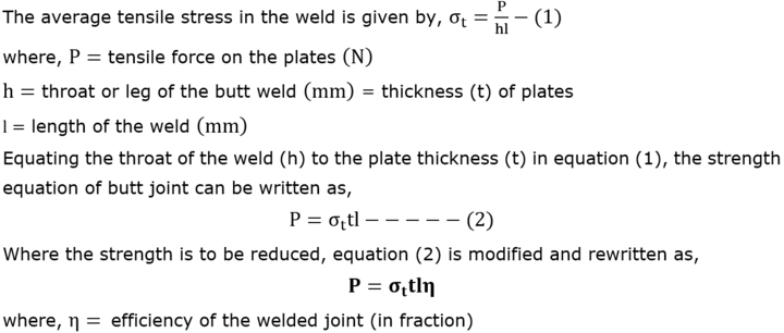
Strength of Butt welds: A butt welded joint, subjected to tensile force P, is shown in the figure:
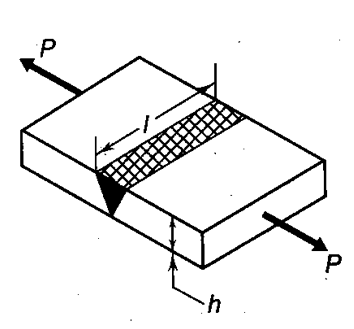
Strength of parallel fillet welds: A parallel fillet weld subjected to a tensile force P is shown in the figure:
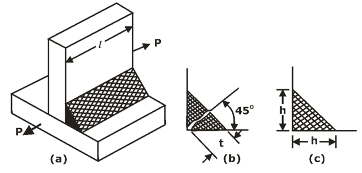
The cross-section of the fillet weld has a right-angled triangle with two equal sides. The length of each of the two equal sides is known as a leg.
Leg length = plate thickness.
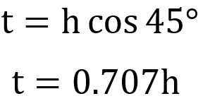
The throat represents the minimum cross-section of the weld generally located at 45° to the leg dimension. Therefore:
The fillet weld failure occurs along the minimum cross-section i.e. the throat due to shear.
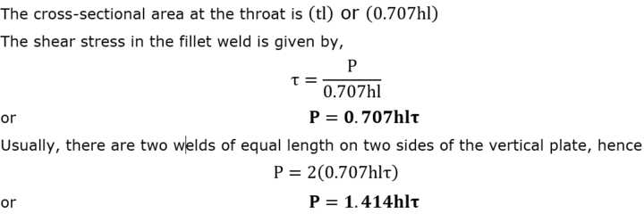
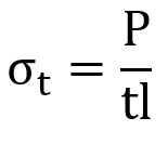
Strength of the transverse fillet welds: A transverse fillet weld subjected to a tensile force P is shown in figure:
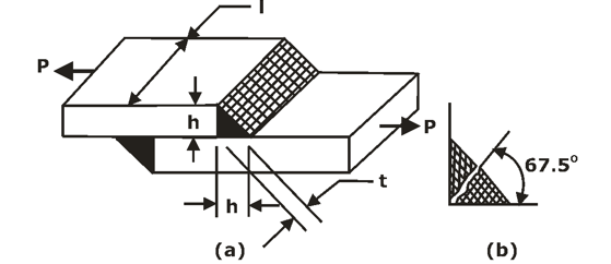
The failure due to tensile stress occurs at the throat section due to being cross-section area minimum. The cross-sectional area at the throat is
The tensile stress in the transverse fillet weld is given by:
The plane of maximum shear stress is inclined at an angle of 67.5° to the leg dimension.
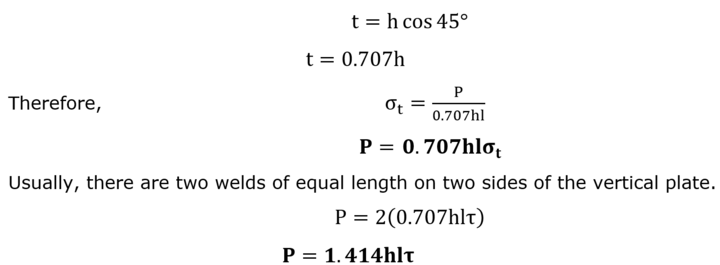
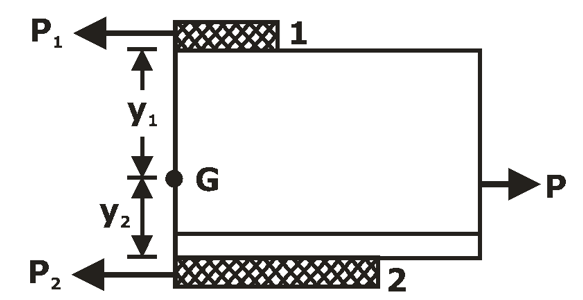
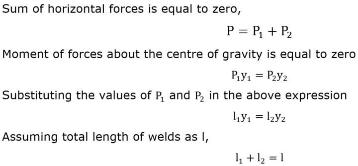
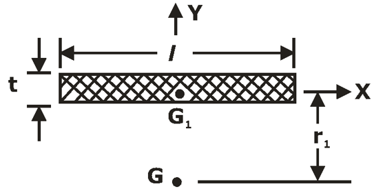
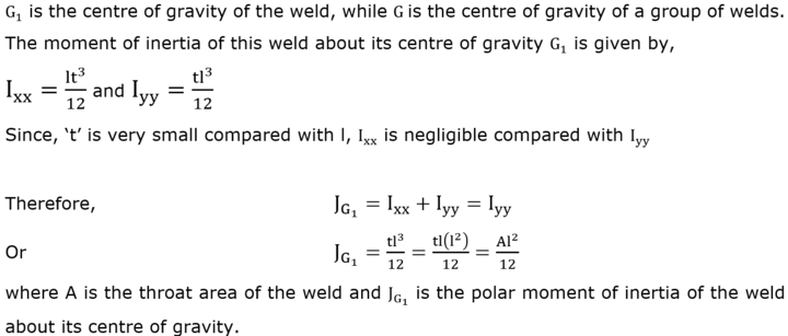
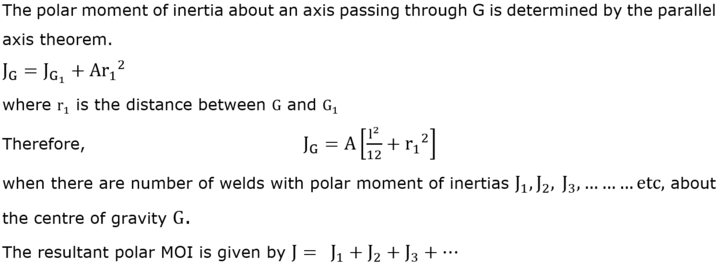
Axially loaded unsymmetrical welded joints
Sections having unsymmetrical welded joints such as angle or T-sections are welded to the steel plates or the beams as shown in the figure. G is the centre of gravity of the angle section:
The external force acting on the joint passes through G and the resisting forces in the welds 1 and 2 respectively:
![]()
The FBD of forces acting on the angle section having two welds are shown in the figure:
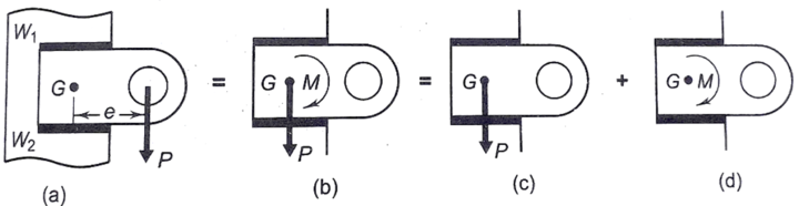
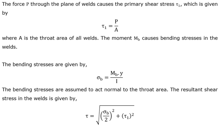
Eccentric load in the plate of welds: A bracket having two fillet welds is acted with an eccentric force P has been shown in the figure:
The primary shear stress due to the eccentric shear stress:
![]()
where A = throat area of all welds
The couple M resulted from the eccentric load causing torsional shear stresses in the throat area of welds and resulted in secondary shear stresses are:
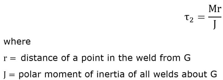
At any point, the resultant shear stress is the vector addition of primary and secondary shear stresses.
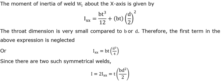
Welding joint subjected to bending moment:
A cantilever beam having a rectangular cross-section welded by two fillet welds W1 and W2 as shown in the figure below:
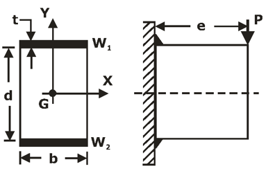
The eccentric force P can be substituted by an equal and similarly directed force (P) acting through the centre of gravity (G) along with a couple given by:
Welding joint subjected to torsional moment:
The shear stress generated in the circumferential fillet weld due to the torsional moment is given by:
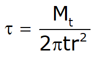
where Mt = Applied torque
r = radius of the shaft
t = throat thickness.
Maximum shear stress in the parallel fillet weld: The maximum shear stress occurs at θ = 45° and it is given by:
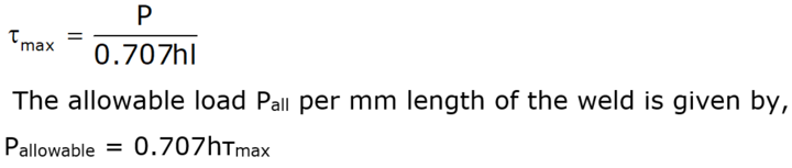
Maximum shear stress in the transverse fillet weld:
The maximum shear stress occurs at θ = 67.5° and it is given by: 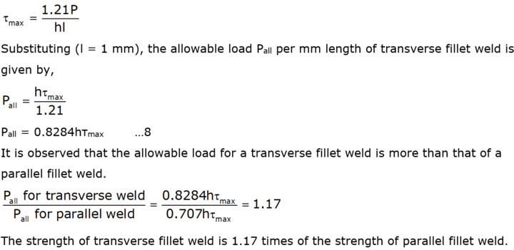
Want to Ace in GATE 2023? BYJU’S Exam Prep offers a comprehensive study plan to aid your GATE exam preparation journey.
We have launched a GATE Starter Series on our App platform FREE for all users. Check the links below:
| GATE Starter Series Link – Civil Engineering | Link |
| GATE Starter Series Link – Mechanical Engineering | Link |
| GATE Starter Series Link – Electronics | Link |
| GATE Starter Series Link – Electrical | Link |
| GATE Starter Series Link – Computer Science | Link |
If you are preparing for ESE/ GATE or other PSU Exams (Mechanical Engineering), then avail Online Classroom Program for ESE and GATE ME:
You can avail Test Series specially designed for all Mechanical Engineering Exams:
Get Unlimited Access to all 161+ Mock Tests
Get complete information about the GATE exam pattern, cut-off, and all those related things on the BYJU’S Exam Prep official youtube channel.


