
- Home/
- GATE ELECTRONICS/
- GATE EC/
- Article
Op amp [Operational Amplifier]
By BYJU'S Exam Prep
Updated on: September 25th, 2023

Operational Amplifiers, also called Op-amp, are one type of differential amplifier that amplifies the difference of the signals provided at its input. Like resistors and capacitors, an Op-amp is a basic building block in many important analog electronic circuits. It can operate on an AC and a DC signal, giving a vast possibility for its applications. Some other differential amplifiers are fully differential amplifiers, instrumentation amplifiers, and isolation amplifiers. When used with different configurations, it can be used to build circuits for mathematical operations, buffers, wave generators, and amplifiers.
This article aims to introduce the reader to Op-amp, its characteristics, and applications and have an informative discussion on its types concerning the way of connections. First, we will start with the definition of an Op-amp, followed by its applications and characteristics. Then we will see its types based on configurations and learn how to open loop and close loops set up for different types of applications.
Download Formulas for GATE Electronics & Communication Engineering – Control System
Table of content
What is Op amp?
Operational amplifiers (Op-amp) are analog circuit blocks that take differential voltage inputs and produce single-ended voltage outputs, the input stage of an operational amplifier is usually a differential amplifier.
It consists of three terminals: two high-impedance inputs and a low-impedance output port. A minus sign denotes the inverting input (-), while the non-inverting input is denoted by a positive sign (+).
Download Formulas for GATE Electronics & Communication Engineering – Digital Circuits
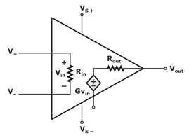
Block Diagram of Op amp
An ideal and a practical Op-amp are shown in the figure below.
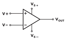
Op amp Symbol
An operational amplifier represents a triangle symbol with inputs, outputs, and supplies.

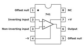
Op amp IC 741 Pin Diagram
The operational amplifier is an 8-pin DIP integrated circuit named IC 741. The pin connections and assigned numbers are shown in the below figure.
Download Formulas for GATE Electronics & Communication Engineering – Electronic Devices
Open Loop and Closed Loop Op amp Configuration
An open loop system has no feedback components, and its output does not influence its operation and inputs. While a closed loop system connects the system’s inputs to its output via a feedback path, this feedback can have a degenerative or constructive effect on the output levels of the system.
The feedback path and element can alter the stability of a system. A negative feedback path is used in Amplifiers, and positive feedback is used for oscillators.
Open Loop Configuration
The magnitude of the open loop gain AOL is very high, so even a small difference at the input terminals will spike the outputs, but due to the saturation condition of the Op amp device, we will get the most positive output +VSupply when the difference (V+-V–) is positive and most negative -VSupply when the difference (V+-V–) is negative.
Closed Loop Configuration
The response of a closed loop Op amp is characterized by a transfer function, representing the system’s gain and the relation between outputs and inputs.
Transfer Function for Inverting Closed Loop Op amp
VOut=(- Rf / R1) VIn
ACL= (- Rf / R1)
Transfer Function for Non-Inverting Closed Loop Op amp
VOut=(1+ Rf / R1) VIn
ACL= (1+ Rf / R1)
Inverting and Non-inverting Op amp
Depending on the input terminal, the configuration inverting or non-inverting is decided.
- Inverting Op amp
When the input is provided only at the inverting terminal (Pin-2), keeping the non-inverting terminal (Pin-3) grounded. - Non-Inverting Op amp
When the input is provided only at the non-inverting terminal (Pin-3), keeping the inverting terminal (Pin-2) grounded.
When the input is provided to both the inputs, the operational amplifier will work as a differential amplifier and hence also be used for calculating the summation and difference of applied signals. The inputs of an op amp are usually differential inputs.
Differentiating Between an Ideal and Practical Op amp
There is no such thing as an ideal Op-amp, but present-day Op-amps are so close to ideal that analyzing an ideal Op-amp becomes similarly accurate as analyzing an actual Op-amp. Op-amps depart from the ideal in two ways. First, dc parameters, such as input offset voltage, are large enough to deviate from the ideal. On the other hand, the idea is based on the assumption that the input offset voltage is zero. Second, as parameters, such as gain, are a function of frequency, they go down from high to low frequencies at dc.
Op amp Characteristics
There are certain important characteristics of an Op-amp, and we will be considering them from the perspective of an ideal case. Since it will simplify the explanation, the results may also be easily seen in approximation with the practical case.
- Open Loop Gain
Open-loop gain refers to the gain of an operational amplifier without any feedback, and ideally, it is considered infinite (very high in a practical case). - Input Impedance
Its ideal value is infinity, which minimizes source loading. An Input impedance is measured between a negative and positive terminal (practically, there is a small leakage current). - Output Impedance
Ideally, an operational amplifier should have zero output impedance, and its output determines its ability to drive current and buffer voltage (practically a very small value). - Frequency Response and Bandwidth (BW)
Ideally, an operational amplifier can maintain a high gain regardless of signal frequency (practically, there is a 20dB/decade decrease after a finite BW, i.e., 3dB point). - Gain Bandwidth Product (GBP)
At a given frequency, GBP is calculated as the point at which the gain of the operational amplifier reaches unity, allowing the user to calculate the device’s open-loop gain. - Common Mode Rejection Ratio (CMRR)
CMRR is the ability of an operational amplifier to cancel out the noise or the common inputs at the terminals. Ideally, the CMRR value is expected to be infinite (practically very good at avoiding noise).
Assumptions for an Ideal Op amp
Voltage Rule
If one of the input potentials changes, the Op-amp output will reverse the polarity to the input and, via a feedback loop, maintain the difference between the input potentials.
Current Rule
Both inputs cannot carry current because their input impedances are infinitely high.
Types of Op-amp
Two possible configurations depending on the terminal where we will provide the input. However, the response and gain can be found similarly using KVL, KCL, and ideal Op-amp assumptions. Now that we have gone through the basics of an ideal Op-amp, we can move ahead and classify them into four main ways. The major types of op-amp are:
- Voltage amplifiers (voltage as input, voltage as output)
- Current amplifiers (current as input, current as output)
- Transconductance amplifiers (voltage as input, current as output)
- Transimpeadance amplifiers (current as input, voltage as output)
Application of Op-amp
The IC 741 Op amp has a huge list of applications, and the list involves operational circuits like Differentiator, Integrators, Rectifiers, Wave Generators, Signal Amplifications, Analog, and Digital Converters, etc. For understanding the applications and respective circuit designs, check out our other articles on Op-amp.
If you are preparing for GATE and ESE, avail Online Classroom Program to get unlimited access to all the live structured courses and mock tests from the following link:
![Op amp [Operational Amplifier]](https://gs-post-images.grdp.co/2020/3/telegram_png30-1-img1585473029191-76.png-rs-high-webp.png)


