- Home/
- GATE ELECTRONICS/
- GATE EC/
- Article
Types of Op Amp
By BYJU'S Exam Prep
Updated on: September 25th, 2023

Operational Amplifiers, also referred to as Op amp, are one type of differential amplifier that amplifies the difference of the signals provided at its input. There can be multiple classifications of types of Op amp based on their configuration, input terminal, and operation. There is also a distinction between different ICs of Op amp according to their designs and characteristics, which are taken care of in the manufacturing process.
We will review various classifications, see how they affect the operation, and briefly discuss their performance and response. First, one should know the basics of operational amplifiers and their characteristics for a better understanding. Each Op amp type has implications and scope of applications utilized for common operational and electrical applications.
Download Formulas for GATE Electronics & Communication Engineering – Analog Circuits
Table of content
What are the Different Types of Op amp?
Types of Op amp means discussing different configurations and arrangements that operational amplifiers can be connected to get the desired application. The classification is generally done on two basis-
- Based on Feedback Topology
- Based on Operation
Types of Op amp Based on Feedback Topology
Feedback is the influence of output on the input of a system. Based on the type of feedback connection, the system response can be varied, and even the system’s stability can be altered. There can be two types of feedback- positive and negative. The positive feedback is related to oscillatory circuits, and the negative feedback is by the amplifier circuits, which are generally damped and stable systems. Types of Op-amp related to feedback can be categorized as follows:
Op amp with no Feedback
Op amp without feedback element or path does not receive any correction and continues to work as a basic comparator circuit. The input difference will drive the response to a positive or negative saturation due to a very high open loop gain. The response time and slew rate are both low for comparators, making them suitable for digital outputs.
Op amp with Positive Feedback
A positive feedback op amp tends to remain in whichever output state it is already in. It latches between saturated positive or saturated negative states. An effective comparator circuit can use this hysteresis to its advantage. Furthermore, it can be used in wave generators, as positive feedback adds oscillatory nature to the circuit. A generic positive feedback Op amp is shown in the figure below, where the input can be connected at the terminals. If inverting input is connected to the ground, we will have a bistable multivibrator since it will drive the response to positive or negative saturation.
Op amp with Negative Feedback
Negative feedback results in a condition of equilibrium (balance) since the output is directed in a certain direction. By balancing both input voltages, the circuit keeps its output voltage from saturating in the negative feedback case. Instead, it drives it to an appropriate level to balance the two inputs.
Download Formulas for GATE Electronics & Communication Engineering – Signals Systems
Types of Op amp Based on Operation
We can move ahead and classify them based on the input, output, and operations in four main ways:
- Voltage amplifiers (voltage as input, voltage as output)
- Current amplifiers (current as input, current as output)
- Transconductance amplifiers (voltage as input, present as output)
- Transresistance amplifiers (current as input, voltage as output)
Two possible configurations depending on the terminal where we will provide the input. However, the response and gain can be found similarly using KVL, KCL, and ideal Op amp assumptions.
Voltage Amplifiers
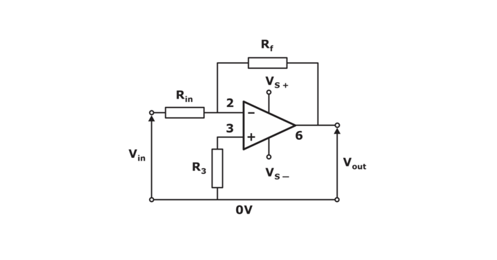
A voltage amplifier will take voltage input and produce a voltage output. It can be of two types depending on which terminal we have applied the input to, the inverting terminal or the non-inverting terminal. In this types of Op amp, the gain expression can be easily derived using the basic KVL and KCL in association with the assumptions of an ideal case.
Voltage Amplifier Circuit

Voltage Amplifier Gain
Vout = Vin (-Rf/Rin)
G = Vout/Vin = -Rf/Rin
Current Amplifier
A current amplifier will take current input and produce a current output. Below we can see the basic circuitry for a current amplifier and calculate the gain. The circuit diagram and gain for this types of Op amp are discussed below.
Current Amplifier Circuit
Current Amplifier Gain
Iout = -Vout /RL
Vout = Iin (Rf)
G = Iout/ Iin= -1/Rf
Transconductance Amplifier
A transconductance amplifier will take a voltage input and produce a current output. Below we can see a basic diagram for the circuit. In this types of Op amp, the gain can be found by using the ideal case’s response and simple KVL at the output.
Transconductance Amplifier Circuit
Transconductance Amplifier Gain
Iout = (v+ – v–).gm ; where gm is the transconductance of the amplifier
Vout = Iout.RL
G = Vout/(v+ – v–) = gm. RL
Transimpedance Amplifier
A trans-impedance amplifier is a types of Op amp that will take current input and will produce voltage output. For example, a basic trans-impedance or trans resistance amplifier is shown in the below figure; considering the ideal case, the input current to the device would be zero, and the inverting terminal would be virtually ground; this will give us an output expression of a simple ohms law and would be the current times the feedback resistance.
Transimpedance Amplifier Circuit
Transimpedance Amplifier Gain
Vout = -Iin.Rf
G =Vout/Iin= -Rf
Download Formulas for GATE Electronics & Communication Engineering – Electronic Devices


