
- Home/
- GATE MECHANICAL/
- GATE ME/
- Article
What is Carnot Cycle? – Efficiency, Carnot Engine, Uses
By BYJU'S Exam Prep
Updated on: September 25th, 2023

French engineer Sadi Carnot first proposed the Carnot cycle in the 19th century. The Carnot cycle is called a reference cycle. Every cycle tries to reach the efficiency of the Carnot cycle, but it is practically impossible because of the engine’s irreversibility.
The Carnot cycle’s efficiency is maximum compared to other cycles under the same working conditions. The efficiency of the Carnot cycle is 1-Q2/Q1. In this article, the application of the Carnot cycle in steam turbines, gas turbines, and IC engine power plants.
Download Formulas for GATE Mechanical Engineering – Thermodynamics
Table of content
What is a Carnot Cycle?
The Carnot cycle is a reference cycle and it is used in heat engines and steam turbine power plants to represent the thermal changes of a working substance in various processes. A working substance undergoes several changes during supplying heat, expansion, heat rejection, and compression processes. All these processes are represented in a cycle. It is called the Carnot cycle.
The Carnot cycle is a reversible cycle, hence all processes in the cycle are internally and externally reversible. Internal reversibility is associated with friction present inside the engine and no friction inside the engine is assumed in the Carnot cycle, hence all processes are internally reversible. External reversibility is associated with thermal equilibrium conditions and the engine is assumed to be in thermal equilibrium with the surrounding environment. Hence, all processes in the Carnot cycle are assumed to be externally reversible.
Download Formulas for GATE Mechanical Engineering – Refrigerating and Air Conditioning
What is a Carnot Engine?
Carnot engine is a hypothetical engine and it is used as a reference engine for analyzing the changes of working substance in heat engines, IC engines, gas turbines, and steam turbine power plants. Heat is supplied to the working substance so that it can produce some amount of work.
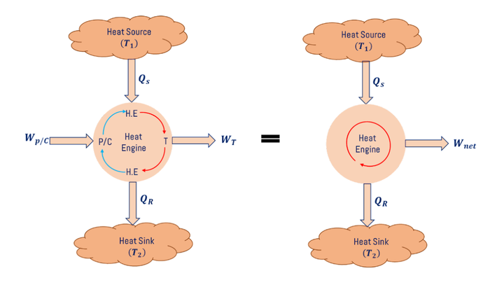
The schematic diagram for the Carnot engine is shown in Fig. above. Qs The amount of heat is supplied to the heat exchanger (H.E) and this heated working substance passes through the nozzle and impinges the turbine blade so that turbine produces WT amount of work then it passes through the heat exchanger (H.E) then QR amount of heat rejected from the working substance then it passes through the compressor in gas turbine power plant and pump in steam turbine power plant, here, we need to give WP/C of work input to run the compressor or pump.
Carnot Cycle in Gas Turbine Power Plant
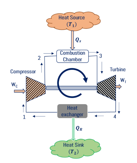
Gas turbine power plant Carnot cycle consists of a compressor, combustion chamber, turbine, and heat exchanger. Air is sucked from the atmosphere and it is compressed in the compressor. Reversible adiabatic compression (1-2) or isentropic compression takes place in the compressor then compressed air is allowed to pass into the combustion chamber then isothermal addition (2-3) takes place in the combustion chamber then compressed and heated gas passed through the nozzle and high-velocity gas is impinging the turbine blades. Reversible adiabatic expansion (3-4) takes place in the turbine. Gas is released into the atmosphere i.e.; isothermal heat rejection (4-1) takes place in the heat rejection process. The schematic diagram for the gas turbine power plant Carnot cycle is shown in Fig. below.
- P-v and T-s diagram for Gas Turbine Power Plant Carnot Cycle:
As we discussed above, isentropic compression (1-2) takes place in the compressor, isothermal heat addition (2-3) in the combustion chamber, isentropic expansion (3-4) in the turbine, and isothermal heat rejection (4-1) in heat exchangers. The P-v and T-s diagrams for the gas turbine power plant Carnot cycle are shown in Fig. below.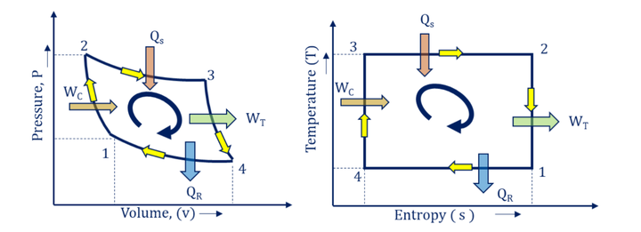
Carnot Cycle in Steam Turbine Power Plant
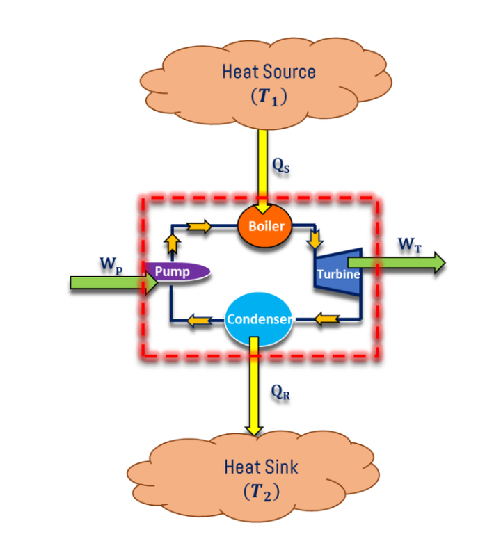
Steam turbine power plant Carnot cycle consists of a boiler, turbine, condenser, and pump. Initially, water is pumped into the boiler then Qs The amount of heat is supplied by combustion of the coal and isothermal heat addition (1-2) takes place in the boiler and it produces the steam from water.
Steam is allowed to pass through the steam nozzle and high-velocity steam is impinging the turbine blades so that reversible adiabatic expansion (2-3) or isentropic expansion takes place in the turbine then steam passes through the condenser, isothermal heat rejection (3-4) takes place in condenser hence, steam converted in water. Water is pumped to the boiler by using a pump; reversible adiabatic pumping (4-1) takes place in the pump. The schematic diagram for the steam turbine power plant Carnot cycle is shown in Fig. below.
Download Formulas for GATE Mechanical Engineering – Power Plant
- P-v and T-s diagram for Steam Turbine Power Plant Carnot Cycle
As we discussed above, isothermal heat addition (1-2) takes place in the boiler, reversible adiabatic expansion (2-3) in a turbine, and isothermal heat rejection (3-4) in the condenser and reversible adiabatic pumping (4-1) in the pump. The P-v and T-s diagrams for the steam turbine power plant Carnot cycle are shown in Fig. below.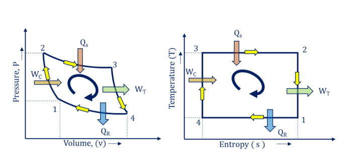
Carnot Cycle in IC Engine Power Plant
In an IC engine power plant, the air is sucked into the cylinder from the atmosphere and the mixing of air-fuel takes place as a part of the suction stroke (0-1) then compression strokes will start. In compression stroke, reversible adiabatic compression (1-2) takes place inside the cylinder. At the end of the compression stroke, spark ignition takes place in petrol engines and fuel injection takes place in diesel engines.
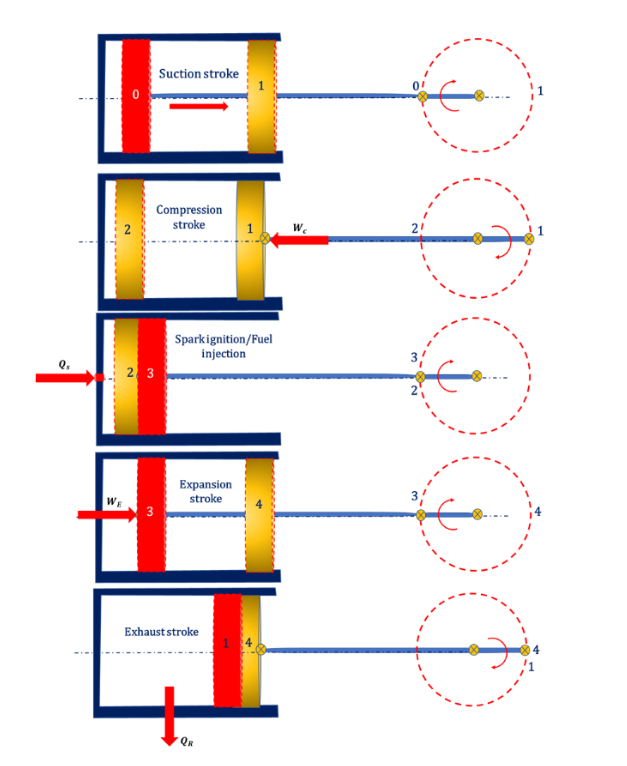
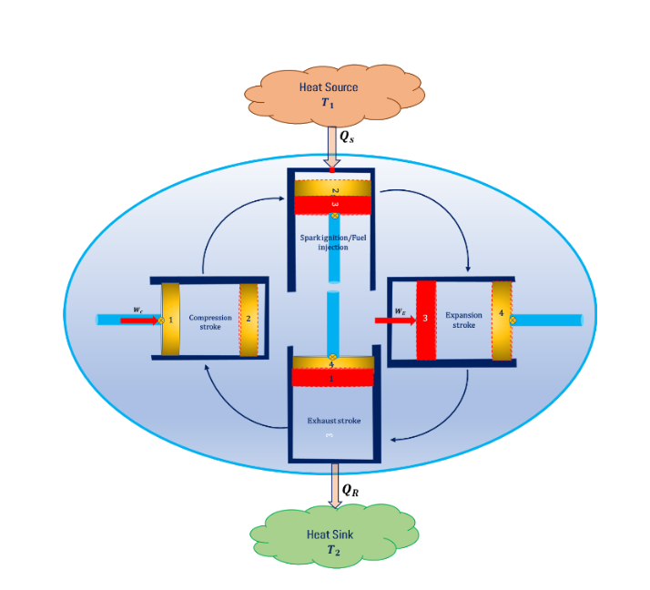
This heat addition process follows isothermal heat addition (2-3) then the fuel is allowed to expand inside the cylinder following the reversible adiabatic expansion process (3-4). The exhaust gasses will be released into the atmosphere in exhaust stroke and it follows the isothermal heat rejection process (4-1). The schematic diagram of the working of the IC is shown in Fig. below.
- P-v and T-s diagram for IC Engine Power Plant Carnot Cycle
As we discussed above, compression stroke follows reversible adiabatic compression or isentropic compression (1-2), spark ignition or fuel injection process follows isothermal heat addition (2-3), Expansion stroke follows reversible adiabatic expansion or isentropic expansion (3-4) and exhaust strokes follow isothermal heat rejection (4-1). The P-v and T-s diagrams for the IC engine power plant Carnot cycle are shown in Fig. below.
Efficiency of Carnot Cycle
To derive an expression for efficiency of the Carnot cycle, consider the amount of heat supplied Qs, heat rejected QR, compression/pump work WC, and expansion work WE. The efficiency of the Carnot cycle is a function of source and sink temperature. The schematic diagram for the Carnot engine is shown in Fig. below.
The procedure to derive an expression for the efficiency of the Carnot cycle is given below.
The efficiency of the Carnot cycle
ηCarnot= Net Work Done/Heat Supplied
ηCarnot= Wnet/Qs
From energy balance
Ein= Eout
Qs= Wnet+ QR
Wnet= Qs– QR
The efficiency of the Carnot cycle
ηCarnot= Wnet/Qs= (Qs-QR)/Qs=1-QR/Qs=1-Q2/Q1
From the concept of reversibility, the magnitude of heat transfer is directly proportional to the absolute temperature.
Q ∝ T
Q = K T
Q2/Q1=T2/T1
The efficiency of the Carnot cycle
ηCarnot=1-Q2/Q1=1 – T2/T1
The expression for the efficiency of the Carnot cycle is the same for steam turbine, gas turbine, and IC engine power plant. The Carnot cycle is a reference cycle and it is also popularly called a hypothetical cycle.
In general, hypothetical cycles are possible only on paper and not possible practically because the Carnot cycle consists of two isothermal and adiabatic processes, as we know that heat transfer is allowed in the isothermal process and no heat transfer in the adiabatic process, It is clearly shown that the material used for constructing the engine behaves as a conductor during the isothermal process and as an insulator during the adiabatic process, there is no material exists in nature it sometimes acts as a conductor and sometimes acts as an insulator hence Carnot cycle is a hypothetical cycle.


