
- Home/
- GATE MECHANICAL/
- Article
Boundary Layer – Definition, Types & Characteristics
By BYJU'S Exam Prep
Updated on: September 25th, 2023

The Boundary Layer theory was first proposed by L.Prandtl in 1904. Boundary layer theory determines the aerodynamic drag (FD) and aerodynamic lift by analyzing hydrodynamic boundary layer formation in flying vehicles. Boundary layer theory is also used to design the vehicle’s shape; for example, after observing the fish’s shape and motion, the aerodynamic foil shape is given to Aeroplan and turbine blades because the aerodynamic foil shape has less drag coefficient (CD). The value of the drag coefficient can be determined by boundary layer theory.
Boundary layer theory has great applications in heat transfer enhancement, i.e., thermal boundary layer formation analysis. The study of hydrodynamic and thermal boundary layer formations over the solid surface shows the relationship between fluid flow’s frictional resistance and heat transfer characteristics. This article overviews hydrodynamic and thermal boundary layer formation over the flat surface and internal flow through pipes.
Table of content
-
1.
What is a Boundary Layer in Boundary Layer Theory?

-
2.
Hydrodynamic Boundary Layer for External Flow
-
3.
Hydrodynamic Boundary Layer for Internal Flow
-
4.
Thermal Boundary Layer for External Flow
-
5.
Thermal Boundary Layer for Internal Flow
-
6.
Results of Hydrodynamic and Thermal Boundary Layer for Laminar External Fluid Flow
What is a Boundary Layer in Boundary Layer Theory?
The boundary layer in boundary layer theory is a thin layer of fluid formed over the solid surface or internal flow through pipes due to velocity or temperature gradient. Boundary layer theory is also used to study the internal flow of fluids. The boundary layer is basically classified as
- Hydrodynamic Boundary Layer
- Thermal Boundary Layer
Hydrodynamic Boundary Layer for External Flow
When the real fluid flows over the solid body, the fluid is adhered to the solid boundary and assumes no-slip condition. i.e., the velocity of the fluid particle which is adhered to the boundary becomes equal to the velocity of the boundary. If the boundary is stationary, the velocity of fluid particles which are adhered to the stationary boundary becomes zero. Boundary layer theory is to determine the loss of energy for fluid flow in channels. The velocity gradients will be developed perpendicular to the solid boundary. The velocity profile for the real fluid flow over the horizontal solid surface is shown below.
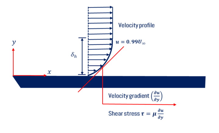
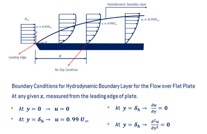
- Hydrodynamic boundary layer thickness (δh) is defined as the distance measured perpendicular to the boundary up to which the fluid velocity becomes 99% of free stream velocity (U∞). To get a hydrodynamic boundary layer, first draw velocity profiles at every point on the solid surface and mark the point perpendicular to the boundary where the fluid has 0.99U∞. The locus of all these points is termed as Hydrodynamic boundary layer. The formation of the boundary layer over the horizontal solid surface/flat plate is shown in the figure below.
Hydrodynamic Boundary Layer for Internal Flow
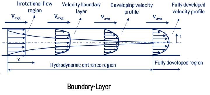
When fluid flows through the circular/non-circular pipe, the pipe’s surface’s velocity is zero, and the maximum velocity (umax) at the pipe center. The average velocity (uavg) fluid is used to analyze fluid flow characteristics. The velocity profile for the fluid which is flowing through the pipe is shown below.
Thermal Boundary Layer for External Flow
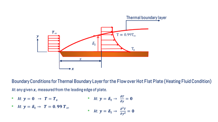
When the fluid with free stream temperature (T∞) flows over the hot solid surface with a temperature (Ts). The temperature gradients will be developed perpendicular to the solid boundary. The temperature profile for the real fluid flow over the horizontal solid surface is shown below.
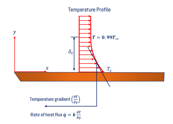
- Thermal boundary layer thickness (δt) is the distance measured perpendicular to the boundary up to which the fluid temperature becomes 99% free stream temperature (T∞). To get the thermal boundary layer, first, draw temperature profiles at every point on the solid surface and mark the point perpendicular to the boundary where the fluid has a temperature of 0.99T∞. The locus of all these points is termed the thermal boundary layers. The formation of a thermal boundary layer over the horizontal solid surface/flat plate is shown in the figure below.
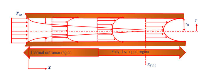
Thermal Boundary Layer for Internal Flow
When fluid flows through the hot circular/non-circular pipe, the temperature at the pipe’s surface temperature of the hot pipe (Ts) and the minimum temperature (Tmin) at the pipe center. The average temperature (Tavg) fluid is used to analyze the thermal characteristics of fluid flow. The temperature profile for the fluid which is flowing through the pipe is shown below.
Relationship between Hydrodynamic (δh) and Thermal (δt) Boundary Layer Thicknesses
L.Prandtl proposed the relationship betweenδhand δtafter analyzing different hydrodynamic and thermal boundary layer formations in different cases. Prandtl number is a dimensionless number, and it is defined as the ratio of momentum diffusivity(ν)and thermal diffusivity(α). The relationship between hydrodynamic and thermal boundary layer thicknesses is given below.
δh/δt=Pr1/3
Here,
- δh= Hydrodynamic boundary layer thickness
- δt= Thermal boundary layer thickness
- Pr= Prandtl number =v/α
Results of Hydrodynamic and Thermal Boundary Layer for Laminar External Fluid Flow
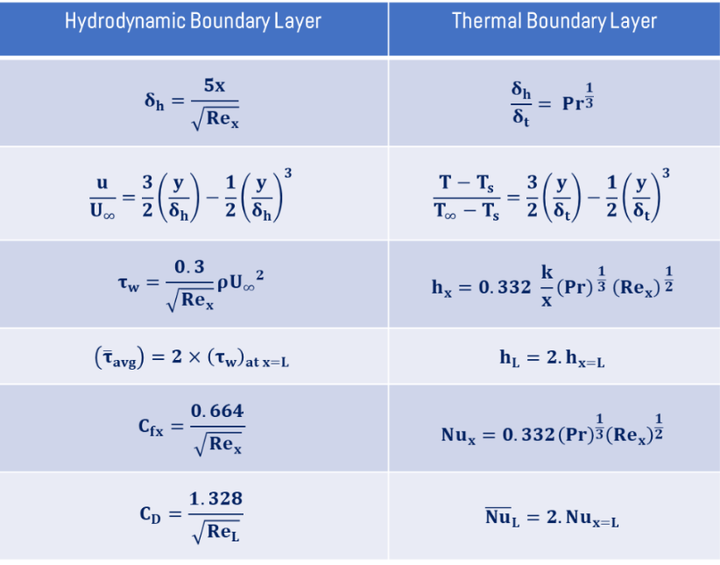
For the laminar hydrodynamic boundary layer, first, the velocity profile is derived by using boundary conditions, the boundary layer thickness (δh), wall and average shear stress, and local and average drag coefficient by using Von Karman and Blasius equations. When the fluid flows over the horizontal flat solid surface, the results for laminar flow in the case of both hydrodynamic and thermal boundary layers are given in the table below.
Here,
- δh= Hydrodynamic boundary layer thickness
- δt= Thermal boundary layer thickness
- u= Velocity of fluid flow
- T= temperature of fluid flow.
- τw= Wall shear stress
- hx= Local heat transfer coefficient
- Rex= Local Reynold’s number
- Pr= Prandtl number
- τavg= Average shear stress
- hL= Average heat transfer coefficient
- Cfx= Local skin friction coefficient
- Nux= Local Nusselt number
- CD= Coefficient of drag
- NuL= Average Nusselt number


