
- Home/
- GATE ELECTRONICS/
- GATE EC/
- Article
What is Static Resistance?
By BYJU'S Exam Prep
Updated on: September 25th, 2023

Static Resistance is defined as the resistance offered by a device when connected to a DC supply. Resistance is the property of devices or any element to offer resistance to the flow of current or, in other words, the flow of charge carriers. This resistive property leads to power dissipation; this power consumption is often undesired, like in cases of non-idealities but can also be sometimes beneficial, such as in cases of heat and light generation.
In this article, we will discuss the static resistance of a diode. A diode is a two-terminal semiconductor device. We will look into the current-voltage characteristics of a diode and define its static resistance for forwarding and reverse-biased conditions.
Download Formulas for GATE Electronics & Communication Engineering – Analog Circuits
Table of content
What is Static Resistance?
When connected to a DC supply, the resistance of a device or element is referred to as static resistance. Resistance is given as the ratio of voltage to current. So under DC supply, the resistance of any device would be the voltage drop across it and the current flowing through it. For a device with ‘V voltage across it and I current flowing through it, the resistance is given as-
Resistance (R) = Voltage (V) / Current (I)
V is the voltage across the device, and I is the current through it.
Diode and its VI Characteristics
A diode is a two-terminal semiconductor device that allows current to flow in only one direction. It is a nonlinear device commonly used as a switch due to its switching characteristics. An ideal diode is expected to offer zero resistance when conducting and infinite resistance when in a non-conducting state; however, non-idealities exist in everything.
Static Resistance PDF
These non-idealities offer a small (non-zero) resistance in their conducting state and very high (non-infinite) resistance when in a non-conducting state. The diode offers a static resistance when connected in forward and reverse bias with a DC supply, and the resistance offered with an AC supply is called dynamic resistance.
Download Formulas for GATE Electronics & Communication Engineering – Signals Systems
VI Characteristics of Diode
The equation gives the VI characteristics of a diode-
I=I0 exp(VD/η VT)
Where
- I0 is reverse saturation current.
- VD is the potential across the diode and is given as the sum of applied potential and the depletion region potential and is given as Vf -VD.
- η is the ideality factor of the semiconductor material.
- VT =0.259 m-volts is the thermal voltage and is given by the einsteins equation equal to kT/q, where k is Boltzmann’s constant (k=1.23 *10-23 J/K).
The below figure shows the graphical characteristics of a practical diode-
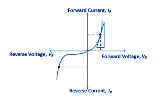
The above figure shows the characteristics of a practical diode. However, there are a few conclusions and points that need to be noted:
- Due to the presence of a depletion region, the diode has an initial threshold voltage that needs to be overcome before a diode can start conducting. VT represents this threshold voltage.
- In forward bias VF, on the right side of the vertical axis, the diode offers some resistance and has a nonlinear curve with a small portion of the linear graph.
- In reverse bias VR on the left of the vertical axis, the diode should ideally be non-conducting, but it allows a small current to flow. If this reverse bias is increased beyond a certain value, the diode goes under breakdown, giving rise to a huge reverse current.
Download Formulas for GATE Electronics & Communication Engineering – Digital Circuits
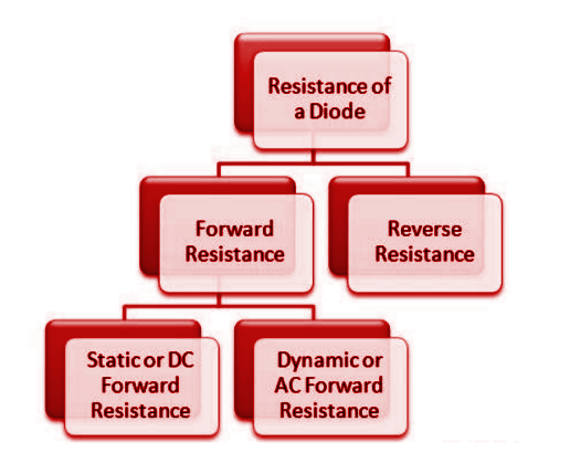
Resistance in a Diode
A diode offers a low resistance in forwarding bias and high resistance in reverse bias. Depending on the supply, these resistances are classified as Static and Dynamic resistance. The classification can be seen in below flow chart-
Forward Resistance
Diodes will not conduct after forward biasing until they reach a minimum threshold voltage level. Once the applied voltage exceeds this threshold level, the diode will conduct. This resistance is referred to as the forward resistance of the diode.
Reverse Resistance
During reverse biasing, a small current will flow through the diode. This can be attributed to the fact that when the diode functions in reverse mode, it is not completely free of charge carriers.
A diode can exhibit reverse resistance characteristics even in this state due to the flow of minority carriers through it.
Static Resistance in Forward Bias
A diode’s static resistance can be determined when connected to a DC source. For instance, suppose the circuit that includes the diode has an external DC voltage. As a result, the Q-[point or operating point of the PN junction diode characteristic curve does not change over time.
Static Resistance in Forward Bias Formula
The mathematical expression for the same is given by-
Rf =Vf/ If
Vf and If are the forward voltage and the forward current, respectively.
Static Resistance in Reverse Bias
When the diode is reverse biased with a DC supply, the resistance offered is referred to as the reverse static resistance.
Static Resistance in Reverse Bias Formula
The mathematical expression for the same is similar to that for the forward resistance and is given by
Rr = Vr / Ir
Vr and Ir are the reverse voltage and the reverse current, respectively.
|
Important GATE Topics |
|
| Lan Full Form | Propped Cantilever Beam |
| Torsional Force | POP Full Form |
| RTC Full Form | Fcfs Scheduling Full Form |
| Types Of Loads | E-Commerce Mcq |
| Laser Full Form | Rankine Formula |


