
- Home/
- GATE MECHANICAL/
- GATE ME/
- Article
Single Slider Crank Mechanism: Definition and Inversions
By BYJU'S Exam Prep
Updated on: September 25th, 2023

A mechanism is something that converts input forces and motion into the required set of output forces and motion. Mechanisms consist of moving parts such as gears and gear trains, belts and chain drives, cams and followers, linkages, and so on. Friction devices like brakes and clutches; structural components such as frames, bolts, bearings, springs, lubricants, Splines, pins, and keys are examples of machine elements.
Single Slider Crank Mechanism PDF
Inversion of the Single Slider Crank Mechanism occurs when a slider-crank linkage’s connecting rod, or coupler, becomes the ground link, connecting the slider directly to the crank. This inverted slider-crank linkage is a type of slider-crank linkage that is frequently used to actuate a hinged joint in construction equipment such as a crane or backhoe, as well as to open and close a swinging gate or door.
Download Formulas for GATE Mechanical Engineering – TOM & Vibrations
Table of content
-
1.
Single Slider Crank Mechanism

-
2.
Inversions of Single Slider Crank Mechanism
-
3.
First Inversion of Single Slider Crank Mechanism
-
4.
Second Inversion of the Single Slider Crank Mechanism
-
5.
Third Inversion of the Single Slider Crank Mechanism
-
6.
Fourth Inversion of the Single Slider Crank Mechanism
-
7.
Single Slider Crank Mechanism Applications
Single Slider Crank Mechanism
The single slider crank mechanism is a four-bar linkage with a rotating crank attached to a slider that moves in a straight line. This mechanism is made up of three major components: the crank, which is the revolving disc, the slider, which slides inside the tube; and the connecting rod, which connects the pieces. The single slider crank mechanism is one of the high-scoring topics of the GATE ME syllabus. The connecting rod drives the wheel around for the first 180 degrees of wheel rotation while the slider travels to the right.
A mechanism is typically part of a larger mechanical system or machine process. A mechanism can also refer to an entire machine, such as a vehicle’s steering mechanism or a watch’s winding mechanism. On the other hand, a machine is frequently characterized as a collection of multiple mechanisms.
The double slider crank mechanism is also possible if two sliders are present in the mechanism. The connecting rod pushes the wheel around to complete the rotation when the slider begins to move back into the tube.

Inversions of Single Slider Crank Mechanism
A mechanism is formed when one of the links in a kinematic chain is fixed. So, by fixing distinct links in a kinematic chain, we can generate as many mechanisms as the number of links in a kinematic chain. Inversion of the mechanism refers to getting alternative mechanisms by fixing different links in a kinematic chain. The single slider crank mechanism inversions formulate various questions in the GATE question paper. Various inversions of this mechanism are also important from the exam perspective.
Download Formulas for GATE Mechanical Engineering – Manufacturing Engineering and Materials
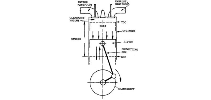
First Inversion of Single Slider Crank Mechanism
This inversion occurs when connection 1 (the ground body) is fixed. Applications include reciprocating engines and reciprocating compressors. Let us see the diagram of the first inversion of the single slider crank mechanism provided below:
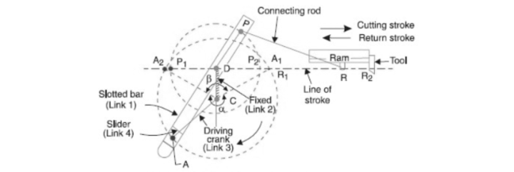
Second Inversion of the Single Slider Crank Mechanism
When link 2 (crank) is fixed, this inversion mechanism occurs. Whitworth rapid return mechanism, Rotary engine, and so on. The diagram of this mechanism is:
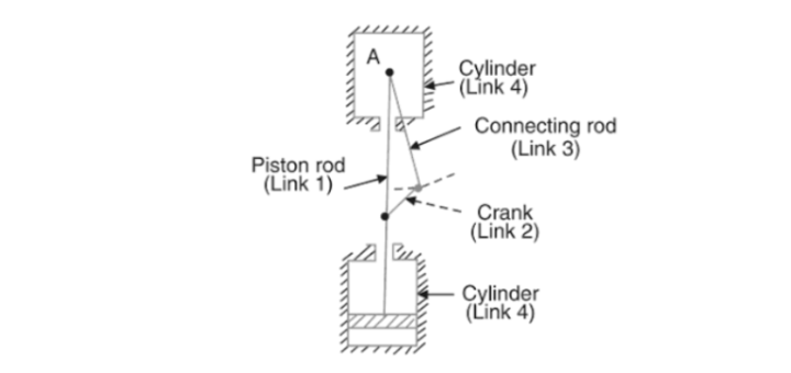
Third Inversion of the Single Slider Crank Mechanism
This inversion occurs when link 3 (the connecting rod) is fastened. Third inversion of single slider crank mechanism is shown below. Applications include slotted crank mechanisms and oscillatory engines.

Fourth Inversion of the Single Slider Crank Mechanism
When link 4 (slider) is fixed, this inversion occurs. Hand pump, pendulum pump, or bull engine, for example. Fourth inversion of the single slider crank mzechanism os shown in the diagram provided below:
Download Formulas for GATE Mechanical Engineering – Strength of Materials
Single Slider Crank Mechanism Applications
A slider-crank mechanism is a mechanical arrangement that converts straight-line motion to rotary motion, as in a reciprocating piston engine, or rotary motion to straight-line motion, as in a reciprocating piston pump. These applications are discreetly elaborated in the GATE notes. The applications of a single slider crank mechanism are as follows:
- Reciprocating Engines/Pumps: The slider-crank mechanism of reciprocating engines/pumps converts straight-line motion to rotary motion and vice versa.
- Combustion Engines: A slider-crank mechanism is utilized in combustion engine piston cylinder assemblies to convert reciprocating motion into circular motion and vice versa.
- Rotary Engines: By securing the crank in the Slider-crank mechanism, rotary engines can be formed. Cars utilize rotary engines.
- Oscillating Cylinder Engine: By securing the connecting rod in the Slider-crank mechanism, oscillating cylinder engines can be created.
- Hand Pump: Attach the slider to the Slider-crank mechanism, which is used to create hand pumps.
Get complete information about the GATE exam pattern, cut-off, and all those related things on the Byju Exam Prep official youtube channel.


