- Home/
- GATE ELECTRONICS/
- GATE EC/
- Article
Simple Diode Circuits – Working, Circuits, Formula, Applications
By BYJU'S Exam Prep
Updated on: September 25th, 2023

Diodes have various applications in power supply circuits, amplifiers, and amplifiers. We would look into some of these simple diode circuits with their types and corresponding output waveforms. Circuits like rectifiers, wave shifters, and shapers fall under simple diode circuits.
To understand discussed simple diode circuits, we will start with a brief revision on diodes and their working. Then, we will also see different diodes being intensively used in the electronics industry. Finally, we will see how changes in diode placement can define the different types of simple diode circuits.
Download Digital circuits Short Notes PDF
Download Formulas for GATE Electronics & Communication Engineering – Control System
Table of content
What is a Diode?
A diode is a two-terminal device made from semiconductors by doping pentavalent and trivalent impurities. Diodes are commonly used for switching but include applications in regulation, rectification, and optical and high-frequency circuits. Diodes conduct in one direction, forward or reverse, depending on the applied potential and required application.
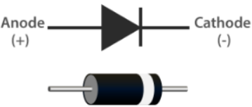
A simple diode is shown, with two terminals, an anode and a cathode. The biasing condition is The difference in potential between the terminals decides reverse or Forward bias.
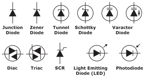
There are different types of diodes, each with different applications. However, a junction diode, also known as a p-n junction diode, is most common and is mostly used in simple diode circuits.
The most simple and common applications of diodes are Rectifiers, Wave Shaping Circuits, and Clampers.
Download Analog Circuits Short Notes PDF
Download Formulas for GATE Electronics & Communication Engineering – Digital Circuits
Rectifiers
Rectifier simple diode circuits convert ac to dc signals utilizing the switching characteristics of a junction diode. Rectifier circuits are the basis of any electronic power supply and are also used in signal processing, for example, demodulation of radio signals.
Different types of rectifiers are discussed below with their basic circuitry and waveform outputs:
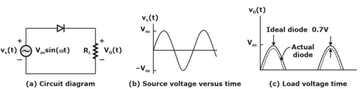
Half Wave Rectifier
A half-wave rectifier passes through an ac signal. Therefore, it requires a single diode for a single-phase ac signal. A half-wave rectifier converts ac signal to pulsating DC signal. A brief explanation of the circuit and response can be seen in the below figure.
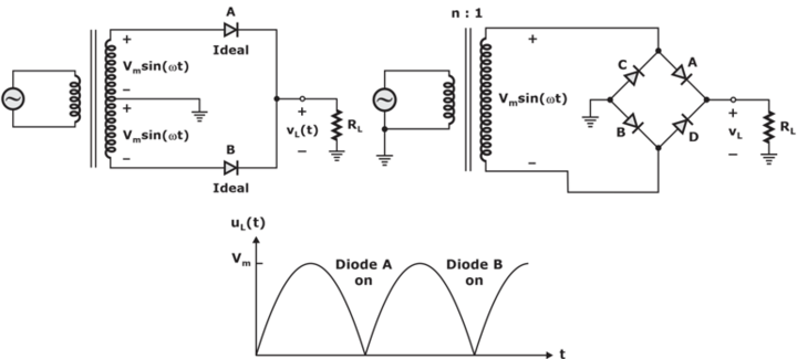
Full Wave Rectifier
It converts both cycles of ac signal to pulsating DC and mathematically corresponds to the absolute value function. It requires four diodes or two diodes and a centre-taped transformer.
Download Formulas for GATE Electronics & Communication Engineering – Electronic Devices
Wave Shaping Circuits/Clipper Circuits
Such simple diode circuits convert one form of a wave to another. Wave shaping circuits find application in generating test signals. Some basic wave shaping circuits are briefed in the discussion below-
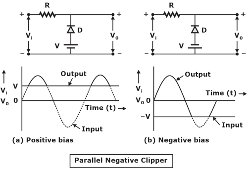
Clipping Circuits chop some portion of the input signal allowing only the portion between, above, or below a certain level of potential. For example, We can consider a half wave rectifier circuit a positive or negative clipping circuit since it clips off either the negative or positive part of the ac signals. The portion to be clipped is decided by the value of resistance and reference voltages connected in the circuitry.
Types of Clipper Simple Diode Circuits
The four types of clipper circuits are listed below.
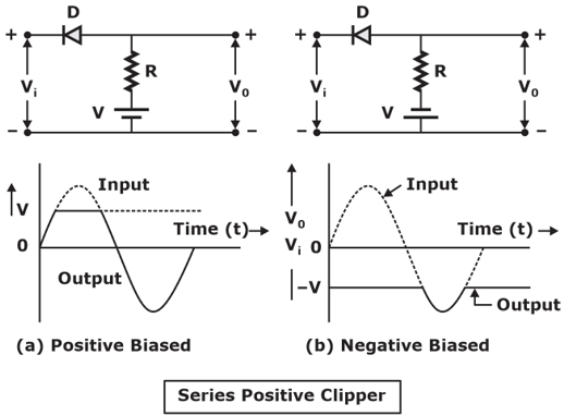
- Series Positive Clipper Circuit
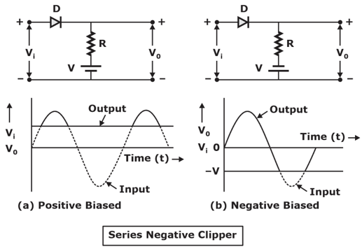
- Series Negative Clipper Circuit
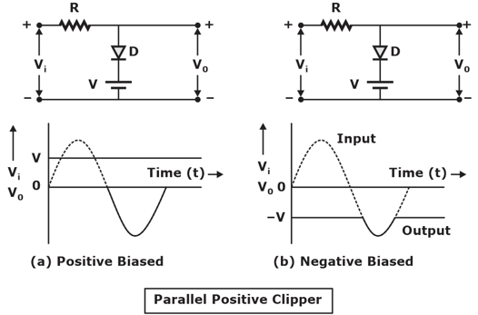
- Parallel Positive Clipper Circuit
- Parallel Negative Clipper Circuit
Below we can see the types of clipping circuits based on the portion to be clipped and how changing the arrangement of certain elements can entirely change the output we get:
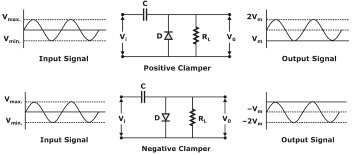
Clamping Circuits
Clamping simple diode circuits add a DC shift in ac signals; it does not change the wave’s shape but instead shifts it above or below a reference voltage. There are two types of clamper circuits depending on the type of DC shift. A clamper circuit is also known as a DC shifter and can shift the signal towards positive or negative polarity; they are also classified as Positive Clamper and Negative Clamper.
Types of Clamping Simple Diode Circuits
Based on the DC shift in the wave, the two types of clamper circuits are listed below.
- Positive Clamper
- Negative Clamper