
- Home/
- GATE ELECTRONICS/
- GATE EC/
- Article
What is RLC Circuit?
By BYJU'S Exam Prep
Updated on: September 25th, 2023

As the name implies, the RLC circuit consists of the passive elements Resistor (R), Inductor (L), and Capacitor (C). If we study and understand the behavior of these passive components individually, then we can design the filters, oscillators, etc., by combining these passive elements. Hence, RLC circuits play a vital role in network design/synthesis.
In this article, get an overview of RLC circuits of basic configurations and how to calculate the voltage or current of each element present in the circuit. You will also learn the relation between voltage and current of the overall circuit. Using this information, we can conclude that the power factor in an RLC circuit is either lagging / leading or unity.
Download Formulas for GATE Electronics & Communication Engineering – Control System
Table of content
What is RLC Circuit?
RLC circuit consists of three electrical components, a resistor (R), an inductor (L), and a capacitor (C), which are connected in series or parallel with each other. The circuit’s name is derived from the letters used to describe the components. The order or arrangement of the RLC circuit components can vary.
In this case, the circuit functions as a harmonic oscillator, which resonates similarly to an LC circuit. When a resistor is introduced, this oscillation is dampened. The circuit is characterized by its impedance and quality factor, which determines the damping; Under damped, Over damped, or Critically damped.
Types of RLC Circuits
Resistor (R), Inductor (L), and Capacitor (C) are the passive elements. We can connect these passive elements in several ways. For the time being, let us consider the basic connections. These are series connections and parallel connections.
If an AC source is present in any electrical network/circuit, it is known as an AC network/circuit. Since we have two basic connections, we will have two types of RLC circuits. Now, let’s discuss the following two types of RLC circuits.
- Series RLC Circuit
- Parallel RLC Circuit
Download Formulas for GATE Electronics & Communication Engineering – Digital Circuits
Series RLC Circuit
In the series RLC circuit, we will connect the AC voltage source, Resistor (R), Inductor (L), and Capacitor (C) all in series. This circuit diagram is shown in the figure below. It is also called the RLC circuit in series. We know that the current is the same in series whereas the supply voltage (AC) gets divided among the passive elements.
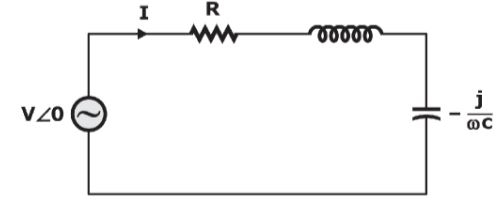
- Since, R, L, and C are connected in series, the equivalent impedance will be Z=R+j(ωL-1/ωC).
- By using ohm’s law, we will get V=IZ=I[R+j(ωL-1/ωC)]
- =>V=VR+j(VL-VC)
- =>V=VR2+(VL-VC)2
- If VL=VC, then V=VR=IR. Here, voltage and current are in phase. Hence, the power factor in an RLC circuit is said to be a unity power factor.
- If VL>VC, then the resultant value of VL-VC will be positive. Since current lags voltage, the power factor in the RLC circuit is said to be a lagging power factor.
- If VL>VC, then the resultant value of VL-VC will be positive. Since current leads to voltage, the power factor in the RLC circuit is said to be the leading power factor.
Download Formulas for GATE Electronics & Communication Engineering – Electronic Devices
Expression for Impedance in the RLC Series Circuit
Write the expression for impedance in the RLC series circuit
Z = √[R2+(XL–XC)2]
Where
- R = resistance,
- XL = inductive reactance
- XC = capacitive reactance.
Parallel RLC Circuit
In a parallel RLC circuit, we will connect the AC source, Resistor (R), Inductor (L), and Capacitor (C) all in parallel. This circuit diagram is shown in the figure below. It is also called an RLC circuit in parallel. We know that voltage is the same in parallel, whereas the supply current (AC) gets divided among the passive elements.
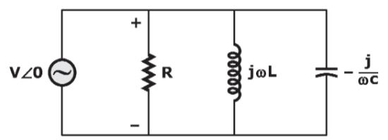
- Since R, L and C are connected in parallel; the equivalent admittance will be Y=1/R+j(ωC-1/ωL).
- By using ohm’s law, we will get I=VY=V[1/R+j(ωC-1/ωL)]
- =>I=IR+j(IC-IL)
- =>I=IR2+(IC-IL)2
- If IC=IL, then I=IR=V/R. Here, current and voltage are in phase. Hence, the power factor in an RLC circuit is said to be a unity power factor.
- If IC>IL, the resultant value of IC-IL will be positive. Since current lags voltage, the power factor in the RLC circuit is said to be a lagging power factor.
- If IC>IL, the resultant value of IC-IL will be positive. Since current leads to voltage, the power factor in the RLC circuit is said to be the leading power factor.
Expression for Impedance in the RLC Parallel Circuit
The expression for impedance in RLC parallel circuit is given by:
1/Z = √[(1/R)2+((1/XL)-(1/XC))2]
1/Z = Y = √[(1/R)2+((1/XL)-(1/XC))2]
Where
- 1/Z = Y = Admittance
- R = resistance,
- XL = inductive reactance
- XC = capacitive reactance.
Resonance in RLC Circuit
When a system can store and transfer energy between two or more different modes of storage, it gives rise to resonance. Resonance in the RLC circuit implies that the natural frequency of the RLC circuit has become equal to the applied alternating source, which happens when the inductive and capacitive reactance becomes the same and cancels out each other.
Resonance is also the condition for delivering maximum power to a passive element. The resonant frequency can be calculated by equating the inductive and capacitive reactances. It is denoted by ƒ0 and comes as (1/2π)√(1/LC).
In this article, we discussed the two RLC circuits, which have series connections first and then parallel connections. We can find the voltage or current of each element present in the circuit by using the respective formula. In each circuit, we can know the relation between voltage and current of the following circuit.


