
- Home/
- GATE MECHANICAL/
- GATE ME/
- Article
Ideal Rankine Cycle
By BYJU'S Exam Prep
Updated on: September 25th, 2023

The Rankine Cycle was first proposed and developed by Scottish engineer William J.M. Rankine in the 19th century. The Ideal Rankine cycle is used in steam turbine power plants to represent the thermal changes of working substances in various processes. A steam turbine power plant consists of a boiler, steam turbine, condenser and pump. A working substance undergoes several changes during supplying heat in the boiler, expansion of steam in the turbine, and heat rejection in the condenser. All these processes are represented in a cycle. It is called the Rankine cycle.
The working substance in a steam turbine power plant is steam and the objective of the plant is to generate power. Here, the thermal energy of steam is converted into kinetic energy in steam nozzles, then this high-velocity steam is allowed to impinge the steam turbine blades so that the kinetic energy of steam is converted into mechanical energy. In this article, the ideal Rankine cycle is discussed in detail.
Download Formulas for GATE Mechanical Engineering- Heat Transfer
Table of content
What is Rankine Cycle?
The Rankine cycle analyses the changes in working substances in steam turbine power plants. First, heat is supplied to the working substance so that it can produce some amount of work.
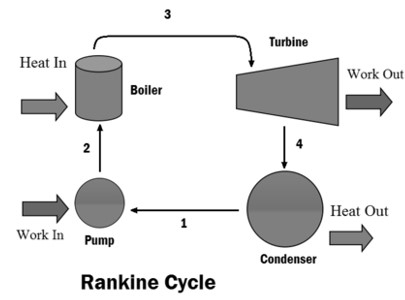
Figure: Rankine Cycle
Qs amount of heat is supplied to the boiler then water converted into steam, this high thermal energy steam passes through nozzle then this high-velocity stream impinging the turbine blade so that turbine produces WT amount of work then it passes through the condenser, QR amount of heat rejected from the steam so that steam is converted into water then this water pumped into the boiler by using a hydraulic pump. WP amount of work input is required to run the pump.
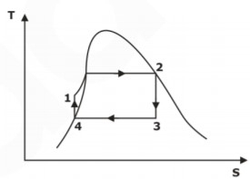
Figure: Rankine Cycle
-
Process 2-3: Isobaric Heat Transfer:
High-pressure liquid enters the boiler from the feed pump (1-2) and is heated to the saturation temperature (2). Further addition of energy causes evaporation of the liquid until it is fully converted to saturated steam (3). -
Process 3-4:Isentropic Expansion:
The vapour is expanded in the turbine, thus producing work that may be converted to electricity. However, in practice, the expansion is limited by the cooling medium’s temperature and by the turbine blades’ erosion by liquid entrainment in the vapour stream as the process moves further into the two-phase region. Therefore, exit vapour qualities should be greater than 90% to avoid blade erosion. -
Process 4-1:Isobaric Heat Rejection:
The vapour-liquid mixture leaving the turbine (3-4) is condensed at low pressure, usually in a surface condenser using cooling water. In well-designed and maintained condensers, the pressure of the vapour is well below atmospheric pressure, approaching the saturation pressure of the operating fluid at the cooling water temperature. -
Process 1-2:Isentropic Compression:
The pressure of the condensate is raised in the feed pump. However, because of the low volume of liquids, the pump work is relatively small and often neglected in thermodynamic calculations.Work done on the pump per kg of water: WP= h2 – h1
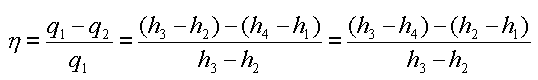
Energy added in steam generator: q1= h3 – h2
Work delivered by turbine: WT= h3 – h4
Energy rejected in the condenser, q2 =h4 – h1
- The thermal efficiency of the Rankine cycle is given by:
Download Formulas for GATE Mechanical Engineering – Thermodynamics
Ideal Rankine Cycle
A steam turbine power plant consists of a boiler, turbine, condenser and pump. Reversible isobaric heat addition (1-2) takes place in the boiler, then the steam passes through the nozzle, and high-velocity steam impinges the turbine blades. Reversible adiabatic or isentropic expansion (2-3) occurs in the turbine. Steam is allowed to pass into the condenser, and reversible isobaric heat rejection (3-4) occurs in the condenser. Steam is converted into the water in a condenser, and water is pumped into the boiler using a hydraulic pump. Reversible adiabatic pumping (4-1) takes place in the pump.
h-s and T-s Diagram for Ideal Rankine Cycle
As we discussed above, reversible isobaric heat addition (1-2) takes place in a boiler, reversible adiabatic expansion or isentropic expansion (2-3) in a turbine, reversible isobaric heat rejection (3-4) in the condenser and reversible isentropic pumping (4-1) in the heat pump. The h-s and T-s diagrams for the ideal Rankine cycle are shown in Fig. below.
Download Formulas for GATE Mechanical Engineering – Fluid Mechanics and Machinery
The efficiency of the Ideal Rankine Cycle
The efficiency of the ideal Rankine cycle is defined as the ratio of net work done by the steam turbine power plant Wnetand heat supplied to the boiler Qs. The difference between turbine workout WT and pump work input Wp is defined as net work done Wnet.
The procedure to determine the expression for efficiency of the ideal Rankine cycle is given below.
The process (1-2): reversible isobaric heat addition (Boiler)
Amount of heat supplied in the boiler:
Apply SFEE
h1+Qs=h2
Qs=h2-h1
The process (2-3): reversible adiabatic expansion (isentropic expansion) (turbine)
Amount of work done by the turbine:
Apply SFEE
h2=WT+h3
WT=h2-h3
The process (3-4): reversible isobaric heat rejection (Condenser)
Amount of heat rejected in condenser:
Apply SFEE
h3=QR+h4
QR=h3-h4= h3-hf4
The process (4-1): reversible adiabatic pumping or isentropic pumping (Pump)
Amount of work input in pump:
Apply SFEE
h4+WP=h1
Wp=h1-h4=h1-hf4=vf4(Pb-Pc)
Net work done in steam turbine power plant:
Wnet = WT-WP=(h2-h3)-(h1-hf4)
The efficiency of the Rankine cycle
ηRankine=Net Work Done/Heat Supplied
ηRankine=Wnet/Qs=[(h2-h3)-(h1-hf4)]/h2-h1


