
- Home/
- GATE MECHANICAL/
- GATE ME/
- Article
Flow Measurement – Devices, Instruments, Types of Flow Meters
By BYJU'S Exam Prep
Updated on: September 25th, 2023

Flow measurement is nothing but quantification of bulk fluid movement. A variety of ways can be used to measure a flow. Positive displacement flow meters collect a certain fixed volume of fluid and then count the number of times the volume is filled for flow measurement. Fluid is the substance that deforms continuously under the action of shear forces. Flow measurement is also called the study of velocity and discharge of fluid flow.
To measure the fluid’s mass flow rate or volume flow rate, we need to use some flow measurement devices, namely mechanical flow meters, variable area meters, and differential pressure head meters. Here we will focus mainly on the pitot tube, venturi meter, inclined venturi meter, and orifice meter. In this article, the procedure to apply continuity and Bernoulli equations to determine flow measurement is explained in detail.
Download Complete Fluid Mechanics and Machinery Formula Notes PDF
Table of content
What is Flow Measurement?
Measurement of mass flow rate or volume flow rate of fluid flow is defined as Flow Measurement. Flow measurement applications in the water industry range from small dosing and treatment flow in pipes of a few millimeters in diameter to the flow of treated or wastewater in trunk mains and aqueducts of 2m in diameter and above. Large interceptor sewers are frequently utilized in larger cities to collect enormous amounts of effluent and spent water and transport it to wastewater treatment facilities for processing.
Some interceptors have a diameter of several meters, may have a unique shape, and typically run partially full. Due to their widespread and varied application, flow meters are essential to the industry’s complete water cycle. Metering has an indirect or direct impact on resource management, process control, planning for new construction, distribution management, leak detection, financial control, and environmental challenges. The volume flow measurement is done in terms of m3/s. This article aims to build an expression for volume flow rate in the case of the pitot tube, venturi meter, and orifice meter by applying continuity and Bernoulli equations.
- Continuity Equation: Mass balance
min=mout
ρ1A1V1= ρ2A2V2
- Bernoulli’s Equation:
P/ρg+V2/2g+Z = Constant
P1/ρg+V12/2g+Z1= P2/ρg+V22/2g+Z2
- Pitot tube
- Venturi meter
- Orifice meter
Pitot Tube Flow Measurement
Stagnation pressure Pstag is defined as the sum of static pressure Pstatic and dynamic pressure Pdyn. The stagnation point is the point where the total velocity of fluid becomes zero; here, the total kinetic energy of the fluid is converted into pressure energy.
Take two sections 1 and 2, as shown in Fig.
Apply Bernoulli’s equation between 1 and 2
P1/ρg+V12/2g+Z1=P2/ρg+V22/2g+Z2
Here, Z1=Z2 and V2=0
P1/ρg+V12/2g=P2/ρg
P1+1/2ρV12= P2
Stagnation pressure P2
P2=P1+1/2ρV12
P1= Static pressure and Dynamic pressure =1/2ρV12
Dynamic pressure head (h)
h=Pdyn/ρg=1/2ρV12/ρg= V12/2g
The velocity of fluid flow V1
V1=√(2gh)
Venturi Meter Flow Measurement
The flow measurement using the Venturi meter is used to measure the mass flow rate or volume flow rate of fluid flow. Venturi meter consists of convergent portion, throat, and divergent portion and takes two sections 1 and 2 as shown in Fig. Apply Bernoulli’s equation between 1 and 2.
P1/ρg+V12/2g+Z1=P2/ρg+V22/2g+Z2
Here, Z1=Z2
P1/ρg-P2/ρg=V12/2g-V22/2g
(P1-P2)/ρg= (V12-V22)/2g
Continuity equation
A1V1=A2V2
V2=A1V1/A2
The difference in pressure head (h) b/w two sections 1 and 2
h=(P1-P2)/ρg= V22/2g-V12/2g
h=(P1-P2)/ρg= (V22-V12)/2g=[(A1V1/A2)2-V12]/2g=V12/2g[(A1/A2)2-1]
The velocity of fluid flow V1 at sections 1-1
V1=√2gh/√[(A1V1/A2)2-1]=A2√2gh/√(A12– A22)
The volume flow rate or Discharge of fluid flow
Q=A1V1
Q=A1A2√2gh/√(A12– A22)
Coefficient of discharge Cd is defined as the ratio of actual flow rate Qactual and theoretical flow rate Q.
Cd=Qactual/Q
Qactual=CdQ
Qactual=CdA1A2√2gh/√(A12– A22)
Orifice Meter Flow Measurement
The flow measurement using an orifice meter measures the mass flow rate or volume flow rate of fluid flow. Take two sections 1 and 2, as shown in Fig. Apply Bernoulli’s equation between 1 and 2.
P1/ρg+V12/2g+Z1=P2/ρg+V22/2g+Z2
Here, Z1=Z2
P1/ρg-P2/ρg=V12/2g-V22/2g
(P1-P2)/ρg= (V12-V22)/2g
The coefficient of contraction is defined as the ratio between the area of the jet at the vena contract and the area of the orifice. Cc= Area at vena contracta/Area of orifice.
Cc=A2/A0
A2=CcA0
Continuity equation
A1V1=A2V2
V1=CcA0V2/A1
h=(P1-P2)/ρg= (V22-V12)/2g=[V22-(CcA0V2/A1)2]/2g=V22/2g[1-CcA0/A1]2
The velocity of fluid flow V2 at sections 2-2
V2=√2gh/√(CcA0/A1)2=A1√2gh/√(CcA0)2
The volume flow rate or Discharge of fluid flow
Q=A2V2=CcA0V2
Q=CcA0√2gh/√[1-(CcA0/A1)2]
The relationship between the coefficient of discharge of orifice meter Cd*and coefficient of contraction Cc
Cd*=Cc×√[1-(A0/A1)2]/√[1-(CcA0/A1)2]
Cc/√[1-(CcA0/A1)2]=Cd*/√[1-(A0/A1)2]
The volume flow rate or Discharge of fluid flow
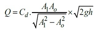
Here,
- A1= Area of a cross-section of a pipe
- A0= Area of a cross-section of orifice meter
- Cd*= Coefficient of discharge of orifice meter


