- Home/
- GATE MECHANICAL/
- GATE ME/
- Article
Brakes and Clutches Study Notes for GATE and Mechanical Engineering Exams
By BYJU'S Exam Prep
Updated on: September 25th, 2023

Welcome to our comprehensive study notes on Brakes and Clutches, specially designed for GATE and Mechanical Engineering aspirants! Brakes and clutches are essential components in mechanical systems, serving crucial functions in controlling motion and transmitting power. These study notes aim to equip students and professionals with a deep understanding of the principles, working mechanisms, types, and applications of brakes and clutches in various engineering fields.
We explore the fundamental concepts behind braking systems used to decelerate or stop rotating machinery efficiently and safely. We delve into various brake types, such as mechanical, hydraulic, pneumatic, and electromagnetic brakes, and analyze their performance characteristics and design considerations. Additionally, we cover the principles of friction materials used in brakes, enabling a comprehensive grasp of the factors influencing braking efficiency. Moving on to clutches, we investigate their vital role in engaging and disengaging power transmission between rotating shafts. Understanding different clutch types, like friction clutches, electromagnetic clutches, and fluid clutches, along with their applications in industrial machinery and automotive systems, forms a core part of this study material. Whether you are preparing for the GATE exam or seeking to strengthen your knowledge in mechanical engineering, these study notes on brakes and clutches will prove invaluable in your pursuit of excellence.
Table of content
Introduction to Brakes
Brakes are vital components in mechanical systems designed to control motion and bring rotating machinery to a stop efficiently and safely. These crucial devices utilize frictional forces or electromagnetic principles to convert kinetic energy into heat, dissipating it to slow down or halt the motion of vehicles, industrial machinery, and various mechanical systems.
Types of brakes
Brakes are essential components used to control motion and ensure safety in various mechanical systems. There are several types of brakes, each designed to suit specific applications. From traditional mechanical brakes to modern hydraulic, pneumatic, and electromagnetic brakes, this introduction provides an overview of the diverse range of braking systems utilized in industries and automotive engineering.
(i). Mechanical Brakes: The working of these brakes is based on mechanical means such as levers, springs and pedals.
(ii) Hydraulic and pneumatic brakes: controlling action is due to fluid pressure such as oil pressure or air pressure.
(iii). Electrical brakes: working is based on magnetic forces and this category of brakes includes magnetic particle brakes, hysteresis brakes and eddy–current brakes.
Block brake with short shoe brake
It is a combination of a simple block and a rotating drum. Here, the block is pressed against the rotating drum with the help of a lever as shown below in the figure:
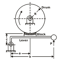
As the block is pressed, the drum motion is retarded due to the friction between the drum and the block. The contact angle of the block and the brake drum is generally small. If the contact angle is < 45°, then the pressure distribution is uniform in the drum due to braking action.
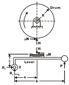
The forces acting on the brake drum,
,
where:
Mt = braking – torque (N-mm)
R= radius of the brake drum (mm)
μ=coefficient of friction,
N= normal reaction (N),
Based on the hinge pin location and coefficient of friction value, there are three different possibilities:
Case I: a > μc, The friction force helps to reduce the magnitude of the actuating force.
Case II: a = μc, The actuating force is zero which signifies that no external force is needed for the braking action and the brake is known as a ‘self–locking’ brake.
Case III: a < μc, The actuating force becomes negative. It is a serious condition that results in uncontrolled braking and grabbing.
Block brake with a long shoe
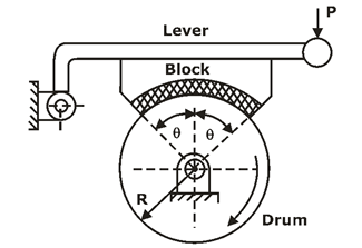
Torque is given as:
Where:
and, θ is the semi–cone angle.
Simple band brakes:
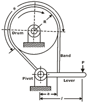
The steel band working is the same as that of a flat belt operation with zero velocity.
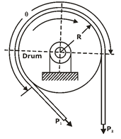
Torque absorbed by the brake is given by:
Differential band brakes
- When neither end of the steel band passes through the fulcrum of the actuating lever, the brake is called the differential band brake.
The free–body diagram of forces acting on the band and the lever is shown in the figure,
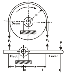
For the self–locking condition:
Disk brakes: A disk brake is similar to a plate clutch with one small modification of replacement of one of the shafts by a fixed member.
Advantages of disk brakes
- The disk brake is simple to install and operate
- Disk brake has high torque transmitting capacity in a small volume
- The brake can never become self–locking
Introduction of the clutch
It is a mechanical device, which is used to connect or disconnect the source of power from the remaining parts of the power transmission system at the operator’s will.
Types of clutch
(i). Positive Contact Clutches: Examples of such clutches are square jaw clutches, spiral jaw clutches and toothed clutches.
(ii). Friction Clutches: They include single and multi-plate clutches, cone clutches and centrifugal clutches.
(iii). Electromagnetic Clutches: Magnetic particle clutches, magnetic hysteresis clutches and eddy current clutches are examples of electromagnetic clutches.
(iv). Fluid Clutches: Hydraulic pressure is the means of power transmission.
The torque transmitting capacity of single plate clutch:
A friction disk of a single plate clutch is shown in the figure:
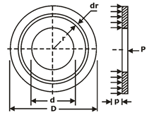
D= Outer diameter of friction disk (mm)
d = inner diameter of friction disk (mm)
P= intensity of pressure at radius (mm)
F = operating force (N)
Mt = torque transmitted by the clutch (N-mm)
The theories used to find the torque capacity of the clutch are Uniform pressure theory (UPT) and Uniform wear theory (UWT).
Uniform Pressure Theory (UPT): In the case of new clutches employing a number of springs, the pressure remains constant over the entire surface area of the friction disk.
Uniform wear theory (UWT): It is assumed that the wear is uniformly distributed over the entire surface area the friction disk. When the wear is uniform:
P.r = Constant
In this case, P is inversely proportional to r. Therefore, maximum pressure occurs at the inner radius while minimum pressure at the outer periphery.
For uniform wear theory or worn–out clutches:
For uniform pressure theory or new clutches:
Note:
Number of disks = number of pairs of contacting surfaces + 1 = Z + 1
Suppose:
Z1= number of disks on the driving shaft
Z2 = number of disks on the driven shaft
Z1 +Z2 = number of pairs of contacting surfaces + 1
Number of pairs of contacting surfaces = Z1 + Z2 – 1
Cone clutches:
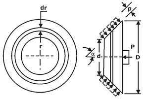
In the case of uniform pressure theory:
In the case of uniform wear theory:
where α is the semi-cone angle.
Centrifugal clutch: It consists of a number of shoes on the inside of a rim of the pulley and the shoe’s outer surfaces are covered with friction material. These shoes (move radially in guides) are held against the boss on the driving shaft by means of spring which causes a constant radially inward force.
the torque transmitting capacity of the clutch is given by,
Notations used
rg = radius of the drum (mm)
rd = radius of the centre of gravity of the shoe in the engaged position (mm)
m= mass of each shoe
Pcf = centrifugal force (N)
Ps = spring force (N)
z= number of shoes
ω2 =running speed (rad/s)
ω1= speed at which engagement starts (rad/s)
If you are preparing for ESE/ GATE or other PSU Exams (Mechanical Engineering), then avail Online Classroom Program for ESE and GATE ME:
Get complete information about the GATE exam pattern, cut-off, and all those related things on the BYJU’S Exam Prep official youtube channel.


