
- Home/
- GATE MECHANICAL/
- GATE ME/
- Article
Welded Joints
By BYJU'S Exam Prep
Updated on: September 25th, 2023

Welded Joints are permanent joints used in the fabrication process. In this modern technology world, fabrication work would be impossible without welding. No single person was involved in the invention of welding. The first is an electric arc welding between two carbon electrodes using the battery as an energy source. It was introduced by ‘Sir Humphry Davy’ in 1880. After the invention, welding continued to evolve, bringing it to its modern-day form.
In the various joining process, welding is one of the most used permanent joining processes. A riveted joint must consist of additional components like cover plates, straps, gusset plates, and clip angle, which increases the assembly’s weight. The welded joint is used as a substitute for a riveted joint.
Download Formulas for GATE Mechanical Engineering – Machine Design
Table of content
What are Welded Joints?
A welded joint is a material joining process formed by fusing two similar or dissimilar, with or without applying pressure and filler metal. Based on the method of joint preparation, welding can be classified into two types:
- Fusion welding – in this welding process, where welding joint is obtained from the melting of the parent metal
- Non-fusion welding – In this welding process joint is produced without melting the parent metal
Types of Welded Joints
As per the requirement, assembly, design, and operating condition, making a proper weld joint is essential. So based on the above parameter, it requires different types of welded joints. The type of welded joints does not depend on the size of weld.
As per the shape of the weld component, the thickness of the weld component plate, and the direction of applied force, we can classify welded joint as follow:
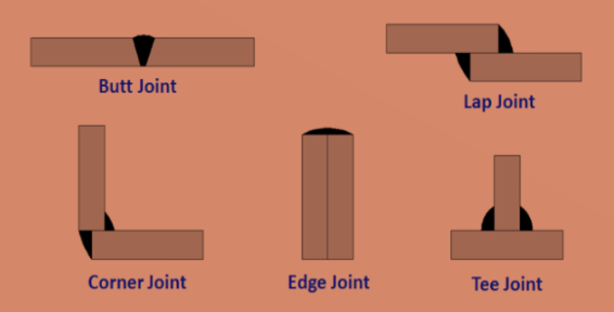
Figure: Types of Welded Joints
- Lap joint
- Butt joint
- Corner joint.
- Edge joint.
- T- joint.
Download Formulas for GATE Mechanical Engineering – Strength of Materials
Lap joint
When the joint is made by overlapping two parts, it is known as a lap joint. It is also known as a fillet joint. Based on the direction of the applied force, There are three different types of fillet weld:
- Single transverse fillet joint.
- Double transverse fillet joint.
- Parallel fillet joint
Transverse fillet weld
It is the type of fillet weld where the direction of applied force is perpendicular to the weld. in transverse loading, one plate exerts a shear load and the other a tensile (or compressive) load on the weld. A double transverse fillet weld is preferable, as there is no edge free to deflect in this case. Transverse fillet welded joints are designed to improve tensile strength.
Parallel fillet weld
In this type of fillet weld, the direction of applied force is parallel to the weld. For parallel loading, both plates exert a shear load on the weld. in this case, weld beads are on both sides of the plate. The asymmetric weld joint is prepared in case of an unsymmetrical section in certain applications such as angle or “T”.
Download Formulas for GATE Mechanical Engineering – Fluid Mechanics and Machinery
Butt joint
When the joint is when the two components lay approximately the same plan, it is known as the butt joint. In this welding, if the thickness of the plate is less than 5 mm, then beveling is required.
In case of plate thickness, 5 mm to 12.5 mm beveling must be provided on one or both sides of the plate. Based on this butt joint can be further classified as:
- Square butt joint.
- Single V-butt joint.
- Double V-butt joint.
- Single U-butt joint.
- Double U-butt joint.
Corner joint
When the corner of both components is joint at perpendicular to each other, then this joint is known as the corner joint.
Tee joint
In a tee joint, when one of the components is perpendicular to the other, and form a “T” like structure, known as a tee joint.
Edge joint
When the edges of both the components are parallel to each other with at least one of their edges in common, the joint is made at the typical edges known as an edge joint.
Welded Joints Symbols
Various welding symbols provide information about the welding process on drawings from the designer to the workmen. It is essential to use the correct welded joint symbols to transfer necessary information. Check out the symbols of various welds in the figure given below:
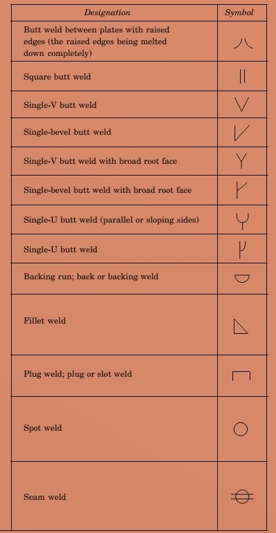
Figure: Welded Joints Symbols
Stress in Welded Joints
Depending on the type of welded joint and loading condition, tensile, compressive and shear stress are developed in the welded joint. It is tough to determine the stresses in the welded joint, as a variable and unpredictable parameter is considered.
- Homogeneities of the weld metal,
- Thermal stresses in the welds,
- Changes in physical properties due to high rate of cooling etc.
While calculating the stresses in the weld joint, we have to consider the following assumptions.
- The load is uniformly distributed over the entire length of the weld.
- The stress is spread uniformly over its effective section.
| Important Topics for Gate Exam | |
| Heat Exchanger | Prims Algorithm |
| Rankine Cycle | Topological Sort |
| Inversion Of Mechanism | Hooke’s Law |
| Kaplan Turbine | Variable In C |
| Types Of Belt Drive | Superposition Theorem |


