
- Home/
- GATE MECHANICAL/
- GATE ME/
- Article
Metal Cutting: Definition, Types and Applications
By BYJU'S Exam Prep
Updated on: September 25th, 2023

Metal cutting is a process of removing metal material by applying a cutting force with a sharp edge. The metal cutting process can be accomplished using various techniques, including mechanical, thermal, and chemical. These techniques are used in many manufacturing industries, including aerospace, automotive, construction, and shipbuilding, to produce various metal products.
Metal Cutting PDF
Metal cutting aims to produce high-quality metal parts with precise dimensions, smooth surfaces, and minimal waste. The selection of the right cutting method depends on the type of metal, the shape and size of the part, and the desired surface finish. The accuracy and efficiency of metal cutting operations are critical to the overall success of a manufacturing process, and cutting technology advances continue to drive productivity and product quality improvements.
Table of content
-
1.
What is Metal Cutting?

-
2.
Classification of the Metal Cutting Process
-
3.
Geometry of Right Hand Single Point Cutting Tool
-
4.
Tool Nomenclature/Angles
-
5.
Types of Metal Cutting Process
-
6.
Merchant’s Analysis for Chip Thickness Ratio
-
7.
Velocity Triangle in Metal Cutting
-
8.
Merchant’s Circle in Metal Cutting
-
9.
Material Removal Rate in Metal Cutting
-
10.
Specific Cutting Energy
-
11.
Different Shear Angle Relation
-
12.
Types of Chips
-
13.
Tool Wear
-
14.
Machinability
-
15.
Applications of Metal Cutting
What is Metal Cutting?
Metal cutting refers to removing metal material from a workpiece to create a desired shape or form. It involves applying a cutting force with a sharp tool, such as a cutting blade or laser, to remove material and create a precise, finished product. This process is crucial in many industries, including manufacturing, construction, and fabrication.
There are various metal cutting methods, including mechanical cutting, thermal cutting, and chemical cutting. The choice of method is dependent on the type of metal being cut, the desired final product, and the equipment available. Regardless of the method, metal cutting requires precision and accuracy to ensure that the final product meets specific dimensional and surface quality requirements. The continued advancements in cutting technology are driving improvements in productivity and product quality in metal-cutting operations.
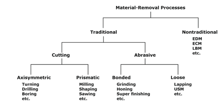
Classification of the Metal Cutting Process
-
Mechanical cutting: This category includes traditional cutting methods that rely on a sharp tool to physically remove material, such as turning, milling, drilling, and grinding.
-
Thermal cutting: This category involves using heat to melt or burn away material, such as oxy-fuel cutting, plasma cutting, and laser cutting.
-
Chemical cutting: This category utilizes chemical reactions to remove metal, such as electrochemical machining and water jet cutting.
-
Abrasive cutting: This category involves using abrasive particles to remove metal, such as abrasive water jet cutting and abrasive wire cutting.
Each category has its own set of advantages and disadvantages, and the choice of method depends on the job’s specific requirements, such as material type, part size and shape, and desired surface finish.
Geometry of Right Hand Single Point Cutting Tool
The geometry of a right-hand single-point cutting tool refers to the shape and design of the cutting edge and its relationship to the workpiece. The following elements define the geometry of a right-hand single-point cutting tool:
-
Nose radius: The rounded portion at the tip of the cutting edge.
-
Cutting edge angle: The angle formed between the cutting edge and the tool axis.
-
Side rake angle: The angle between the side of the tool and a plane perpendicular to the tool axis.
-
End rake angle: The angle between the end face of the tool and a plane perpendicular to the tool axis.
-
Relief angle: The angle between the side and end faces of the tool.
-
Back rake angle: The angle between the back face of the tool and a plane perpendicular to the tool axis.
The geometry of the cutting tool affects the cutting forces, tool wear, and surface finish of the workpiece. The right combination of these elements can result in improved cutting performance and longer tool life.
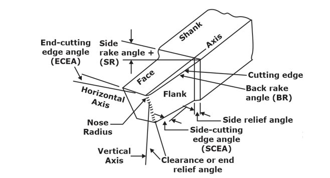
Right-hand single-point cutting tool
Tool Nomenclature/Angles
Tool nomenclature refers to the terms used to describe a cutting tool’s various features and angles. The following are some of the most commonly used terms in tool nomenclature:
-
Tool nose radius: The radius of the rounded tip of the cutting edge.
-
Cutting edge angle: The angle between the cutting edge and the tool axis.
-
Side rake angle: The angle between the side of the tool and a plane perpendicular to the tool axis.
-
End rake angle: The angle between the end face of the tool and a plane perpendicular to the tool axis.
-
Relief angle: The angle between the side and end faces of the tool.
-
Back rake angle: The angle between the back face of the tool and a plane perpendicular to the tool axis.
-
Shank: The portion of the tool that holds and supports the cutting edge.
-
Insert: The replaceable component of the tool that includes the cutting edge.
-
Clearance angle: The angle between the cutting edge and a plane perpendicular to the tool axis at the point where the cutting edge meets the shank.
The proper selection and understanding of these angles are crucial to a cutting tool’s performance and the workpiece’s quality.
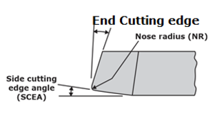
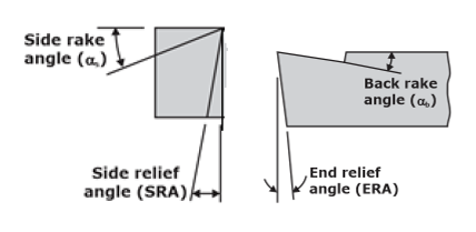
Single Point Cutting Tool
Types of Metal Cutting Process
Metal cutting processes include a variety of methods for removing material from a workpiece, including turning, milling, drilling, grinding, sawing, shearing, punching, and stamping. The choice of process depends on the job’s specific requirements, such as material type, part size and shape, and desired surface finish. There are several types of metal-cutting processes, including:
-
Turning: A process where a single-point cutting tool moves along the surface of a rotating workpiece to remove material and produce a desired shape.
-
Milling: A process where a multi-point cutting tool moves perpendicular to the surface of a workpiece to remove material and produce a desired shape.
-
Drilling: A process where a rotary cutting tool is used to create a cylindrical hole in a workpiece.
-
Grinding: A rotating abrasive wheel removes material from a workpiece to produce a desired surface finish.
-
Sawing: A continuous or reciprocating blade cuts a workpiece into desired lengths.
-
Shearing: A process where a sharp blade is used to cut a workpiece along a straight line.
-
Punching: A sharp tool is used to remove a portion of a workpiece to create a hole or notch.
-
Stamping: A process where a punch and die set is used to deform a workpiece into a desired shape.
Each metal-cutting process has its own set of advantages and disadvantages, and the choice of process depends on the job’s specific requirements, such as material type, part size and shape, and desired surface finish.
Merchant’s Analysis for Chip Thickness Ratio
Merchant analysis calculates the chip thickness ratio (CTR) in metal-cutting operations. CTR is the ratio of the actual chip thickness to the uncut chip thickness and is used to determine the type of chip being produced during cutting. Merchant’s analysis involves plotting the uncut chip thickness versus the true cutting speed to determine the CTR.
In Merchant’s analysis, a family of curves is produced, each representing a different type of chip, such as continuous, discontinuous, or built-up edge. The CTR can be determined by finding the point on the curve that corresponds to the true cutting speed of the operation. The CTR is then used to predict the workpiece’s cutting forces, tool wear, and surface finish.
Merchant’s analysis is a useful tool for optimizing metal cutting operations by enabling the selection of cutting conditions that produce a desired CTR, leading to improved cutting performance and longer tool life.
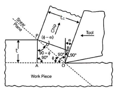
Orthogonal cutting analysis
t = uncut chip thickness
tc = Chip thickness after cutting
ϕ = Shear plane angle
α = Back rake angle
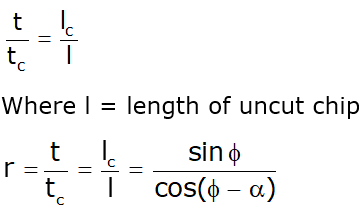
The ratio of ‘t’ to ‘tc’ is called the chip thickness ratio (or simply the chip ratio) it is designated by ‘r’.

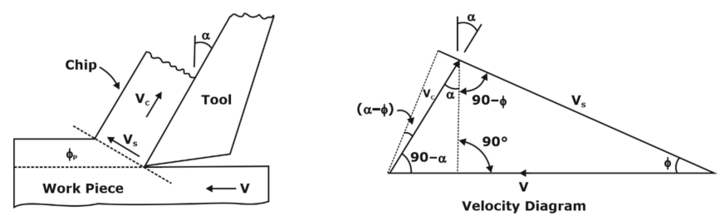
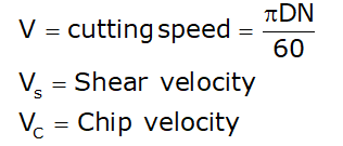
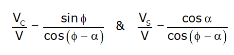
Velocity Triangle in Metal Cutting
-
Tangential cutting velocity: The velocity of the cutting tool at the cutting point, perpendicular to the cutting edge.
-
Feed velocity: The velocity of the cutting tool in the direction of the feed.
-
Approach velocity: The velocity of the cutting tool as it approaches the workpiece equal in magnitude to the feed velocity.
The velocity triangle helps to visualize and understand the relationship between the various components of cutting velocity and their impact on the cutting process. It is used to calculate important parameters, such as cutting speed, feed rate, and chip thickness. The velocity triangle is also used to analyze the effects of changes in cutting conditions, such as cutting speed and tool geometry, on the cutting process.
Overall, the velocity triangle is a useful tool for optimizing metal cutting operations by clearly understanding the complex relationships between cutting velocity, cutting forces, and workpiece geometry.
Velocity triangle
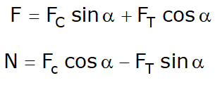
Merchant’s Circle in Metal Cutting
A merchant’s circle is a graphical representation used in metal cutting to analyze the cutting process. It is a circle that visualizes the relationships between cutting speed, uncut chip thickness, and the true cutting speed. Merchant’s circle is derived from Merchant’s analysis, a method used to calculate the chip thickness ratio (CTR) in metal cutting operations.
The Merchant’s circle is a graphical representation of the equation for uncut chip thickness, which is a function of cutting speed and the chip thickness ratio. The circle is drawn by plotting uncut chip thickness as a function of the true cutting speed, with the chip thickness ratio as a parameter. Each point on the circle represents a different combination of uncut chip thickness and true cutting speed for a given CTR.
Merchant’s circle is used to analyze the cutting process by providing a visual representation of the relationships between cutting speed, uncut chip thickness, and the chip thickness ratio. It also optimizes metal cutting operations by selecting cutting conditions that produce a desired CTR and workpiece surface finish.
Overall, Merchant’s circle is a useful tool for understanding the metal cutting process and optimizing cutting conditions to improve cutting performance and tool life.
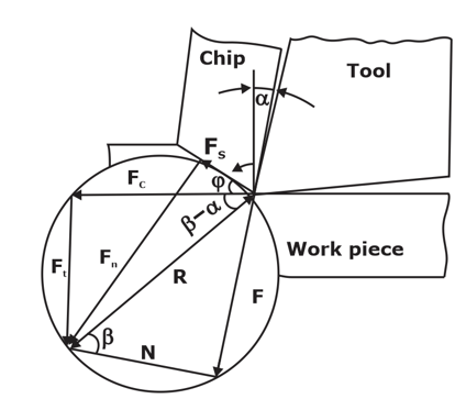
Merchant’s Cutting Force circle
![]()
![]()
Material Removal Rate in Metal Cutting
Material removal rate (MRR) measures the volume of material removed from a workpiece in a metal cutting operation. It is calculated by multiplying the cutting speed by the width of the cut and the depth of the cut. MRR is an important parameter in metal cutting because it affects the productivity of the operation and the overall manufacturing cycle time.MRR can be increased by increasing the cutting speed, width, or depth of the cut. However, increasing MRR may also increase cutting forces, higher tool wear, and decreased surface finish quality. Therefore, it is important to find the optimal combination of cutting parameters that maximizes MRR while also meeting other requirements, such as surface finish quality, cutting tool life, and workpiece dimensional accuracy.
MRR is also important in determining the cutting tool selection and the cutting conditions for a given operation. Different cutting tools and cutting conditions will produce different MRRs, and the optimal choice will depend on the job’s specific requirements, such as material type, part size and shape, and desired surface finish.
In conclusion, MRR is a critical metal-cutting parameter affecting the operation’s productivity, cutting tool life, and workpiece quality. It is important to optimize MRR by considering a range of factors, including cutting speed, cutting tool selection, and cutting conditions.
MMR = fdv
where
- MMR- material removal rate, mm3/s or (mm3/min)
- v – cutting speed, m/s or (mm/s),
- f – feed, mm (mm/revolution);
- d – depth of cut, mm
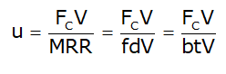
Specific Cutting Energy
The specific cutting energy is a parameter that can be obtained by dividing the total work done by the material removal rate.
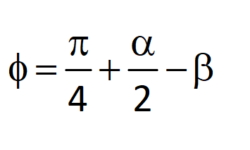
Different Shear Angle Relation
(a) Merchant’s shear angle relation
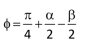
(b) Lee and Shaffer’s relation
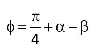
(c) Stabler relation
Types of Chips
Chips are material fragments removed from a workpiece during a metal-cutting operation. Several different types of chips can be produced in metal cutting, including:
-
Continuous chips: Chips that are produced continuously and unbroken, typically seen in low-speed, high-torque cutting operations.
-
Discontinuous chips: Chips that are produced in a broken or fragmented fashion, typically seen in high-speed cutting operations.
-
Built-up edge (BUE) chips: Chips that have multiple layers, resulting from the material being built up on the tool’s cutting edge, causing it to lose its sharpness and reduce cutting performance.
-
Whisker chips: Long, thin, and continuous chips produced in certain materials, such as aluminium and titanium alloys, when using high cutting speeds and low feed rates.
-
Curled chips: Chips that have a curled or spiraled shape, produced in certain cutting conditions and materials, particularly when cutting with low feed rates and high cutting speeds.
-
Ribbon chips: Thin and flat chips produced in certain cutting conditions, typically seen in brittle materials or low toughness.
Chips have different characteristics, such as shape, length, and thickness, affecting cutting performance and tool life. Understanding the different types of chips and how they are produced is important for optimizing metal-cutting operations and improving productivity.
Tool Wear
Tool wear is the gradual loss of material from the cutting tool due to the friction and heat generated during a metal cutting operation. Tool wear can significantly impact cutting performance, as it can cause changes in tool geometry and shape, leading to decreased accuracy and surface finish quality, increased cutting forces, and reduced tool life. There are several types of tool wear, including:
-
Abrasive wear: Wear caused by the hard and abrasive particles in the workpiece material that scrape and remove material from the cutting tool.
-
Adhesive wear: Wear caused by welding workpiece material to the cutting tool, leading to a transfer of material from the workpiece to the tool.
-
Fatigue wear: Wear caused by the repeated cyclic loading and unloading of the cutting tool during the cutting operation, leading to cracks and, eventually, tool failure.
-
Erosive wear: Wear caused by high-speed particles impinging on the cutting tool, causing the material to be removed from the tool surface.
Tool wear can be reduced by selecting the appropriate cutting tool for the job, optimizing cutting parameters such as cutting speed, feed rate, and depth of cut, and using proper coolant and lubrication. Monitoring and controlling tool wear is important for maximizing cutting performance and extending tool life, which can lead to improved productivity and cost savings.
Machinability
Machinability measures how easily a material can be cut and shaped during manufacturing operations, such as metal cutting. It is a critical factor in determining the choice of cutting tool, cutting parameters, and overall manufacturing process. Materials with high machinability can be cut easily and quickly, while materials with low machinability require more time and effort to cut, resulting in decreased productivity and increased costs. Factors that influence machinability include the hardness, strength, and ductility of the material and its chemical composition and microstructure.
The machinability of a material can be improved by using proper cutting tool selection, cutting parameters, coolant and lubrication and by implementing heat treatment and surface finishing processes.
In conclusion, machinability is a critical factor in metal cutting and manufacturing operations, affecting both the productivity and the costs of the process. Understanding the machinability of different materials and how they can be improved is important for optimizing metal-cutting operations and improving overall efficiency.
Applications of Metal Cutting
-
Automotive industry: Used for cutting and shaping metal parts for cars, trucks, and other vehicles.
-
Aerospace industry: Used for cutting and shaping metal components for aircraft, helicopters, and satellites.
-
Construction industry: Used for cutting and shaping metal components for buildings and structures, such as beams, girders, and columns.
-
Energy industry: Used for cutting and shaping metal components for the generation, storage, and distribution of energy, such as turbines, generators, and pipelines.
-
Medical industry: Used for cutting and shaping metal components for medical devices, such as orthopaedic implants, surgical instruments, and dental implants.
-
Electronic industry: Used for cutting and shaping metal components for electronic devices, such as computers, smartphones, and other consumer electronics.
-
Consumer goods industry: Used for cutting and shaping metal components for household appliances, tools, and other consumer goods.
Metal cutting is a versatile and critical manufacturing process used in various applications to produce various products. The ability to produce high-precision components with consistent quality and reliability has made metal cutting a crucial part of modern manufacturing.
Get complete information about the GATE exam pattern, cut-off, and all those related things on the BYJU’S Exam Prep official youtube channel.


