
- Home/
- GATE ELECTRONICS/
- GATE EC/
- Article
What is a JFET Amplifier?
By BYJU'S Exam Prep
Updated on: September 25th, 2023

JFET amplifiers are a lengthy channel of semiconductor material. To create source/drain interconnections, ohmic connections are presented at both extremities of the semiconductor channels. We are using Amplifiers in power systems and communication systems. Since we have three types of transistors, there will be three types of transistor amplifiers. Those are BJT amplifiers, JFET amplifiers and MOSFET amplifiers. This article will discuss the types of JFET Amplifiers and their operation.
The Junction Field Effect Transistor (JFET) can be operated mainly in three regions. Those are the Cut-off, Ohmic and Saturation regions. We must operate the JFET in the Ohmic or linear regions for amplification. We will use the respective JFET amplifier based on the requirement.
Download Formulas for GATE Electronics & Communication Engineering – Control System
Table of content
What is a JFET Amplifier?
As the name implies, the amplifier performs the amplification. It is an electronic circuit in which the transistor is one of the main components. Among types of transistors, JFET is the second one. If JFET is present in an amplifier circuit, it is said to be a JFET amplifier.
Download Formulas for GATE Electronics & Communication Engineering – Electronic Devices
JFET Amplifier Circuit Diagram
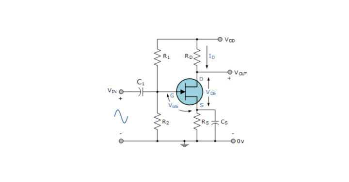
The basic electric quantities are voltage and current. The product of voltage and current is known as power. Using an amplifier, if we get the amplification of input voltage at the output, it is known as a voltage amplifier. Similarly, the current and power amplifiers amplify the current and power at the output.
Types of JFET Amplifiers
We can classify the JFET amplifiers based on different parameters in multiple ways. JFET configuration is one of those parameters. We will get three types of JFET amplifiers since we have three configurations of JFET. One by one, now let us discuss these amplifiers.
- Common Gate (CG) Amplifier
- Common Source (CS) Amplifier
- Common Drain (CD) Amplifier
Download Formulas for GATE Electronics & Communication Engineering – Digital Circuits
Common Gate JFET Amplifier
In the Common Gate JFET configuration, the Gate terminal of JFET is common to both input and output. In this configuration, we will consider the Source and Drain terminals of the JFET amplifier as the input and output terminals. The circuit diagram of the JFET Amplifier, which is configured in Common Gate (CG), is shown below.
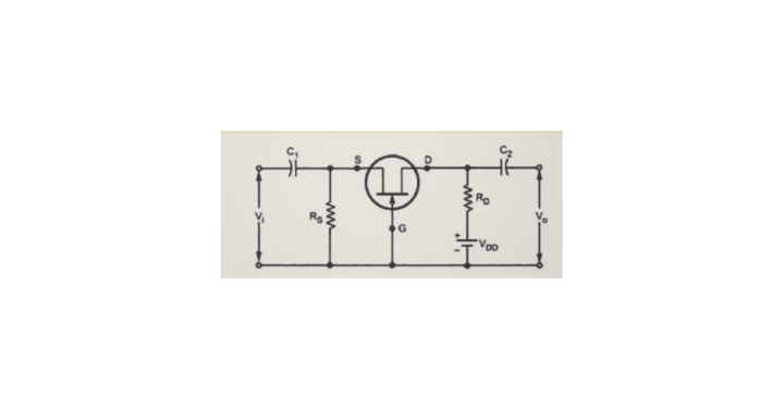
The Common Gate (CG) amplifier is like the Common Base (CB) amplifier. In this JFET amplifier, the AC (sinusoidal) voltage waveform applied at the Source terminal will be amplified and produced at the Drain terminal. There won’t be any phase difference between the input and output waveforms.
This JFET amplifier’s input and output resistances are low and high, respectively. We can use a CG amplifier as a voltage amplifier since it has a high voltage gain. The current gain of this amplifier is approximately equal to one.
Common Source JFET Amplifier
In the Common Source JFET configuration, the Source terminal of JFET is common to both input and output. In this configuration, we will consider the Gate and Drain terminals of the JFET as the input and output terminals. The circuit diagram of the JFET Amplifier, which is configured in Common Source (CS), is shown below.
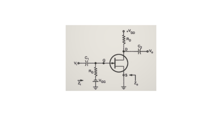
The Common Source JFET amplifier is like the Common Emitter (CE) amplifier. In this JFET Amplifier, the AC (sinusoidal) voltage waveform applied at the Gate terminal will be amplified and produced at the Drain terminal. But there will be an 1800 phase difference between the input and output waveforms.
Both the input and output resistances of this JFET amplifier have a medium value. Even this amplifier’s voltage and current gain are of medium value. We can use a CS amplifier as a power amplifier, just like a CE amplifier, since it has high power gain.
Common Drain JFET Amplifier
In the Common Drain JFET configuration, the Drain terminal of the JFET amplifier is common to both input and output. In this configuration, we will consider the Gate and Source terminals of the JFET as the input and output terminals. The JFET Amplifier’s circuit diagram, configured in Common Drain (CD), is shown below.
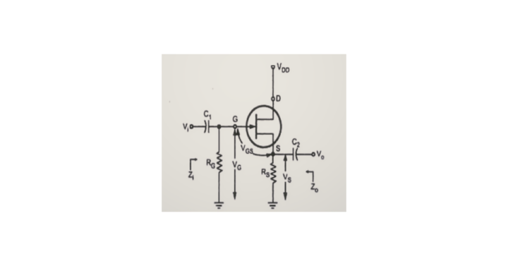
The Common Drain JFET amplifier is like the Common Collector (CC) amplifier. In this JFET amplifier, the AC (sinusoidal) voltage waveform applied at the Gate terminal will be produced at the Source terminal with unity voltage gain. There won’t be any phase difference between the input and output waveforms.
This JFET amplifier’s input and output resistances are high and low, respectively. We can use a CD amplifier as a current amplifier since it has a high current gain. The voltage gain of this amplifier is approximately equal to one.
|
Important GATE Topics |
|
| Portal Frames | Superposition Theorem |
| Binary Search Tree | Work Done By A Constant Force |
| Structural Analysis | Motion Under Gravity |
| Basic Signal Operations | Ideal Diode |


