
- Home/
- GATE MECHANICAL/
- GATE ME/
- Article
Head Losses in Pipes, Bends and Fittings Notes for Mechanical Engineering
By BYJU'S Exam Prep
Updated on: September 25th, 2023

Energy loss is categorized as:
- the sudden expansion of the pipe
- sudden contraction of the pipe
- bend in pipe
- any obstruction in the pipe
Major Loss: It is calculated by Darcy Weisbach’s formulas
Loss of head due to friction: 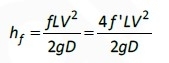
where:
L = Length of pipe
V = Mean velocity of flow
d = Diameter of pipe
f = friction factor
friction factor (f) = 4 ×coefficient of friction (f’)
For Laminar flow: ![]() and coefficient of friction:
and coefficient of friction: ![]() .
.
For turbulent flow, the coefficient of friction: 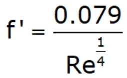
Chezy’s Formula: In fluid dynamics, Chezy’s formula describes the mean flow velocity of steady, turbulent open channel flow.
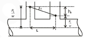
Average velocity V is given by: ![]()
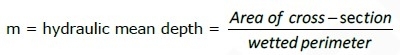
Where: ![]()
i = Loss of head per unit length of pipe ![]() (hydraulic slope tan θ)
(hydraulic slope tan θ)
Relation between Coefficient of Friction and Shear Stress:
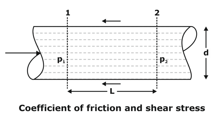
![]()
where: f = Coefficient of friction
τ0 = Shear stress
Minor Loss: Another type of head loss in minor loss is induced due to the following reasons
Loss due to Sudden Enlargement:
Head loss: 
Loss due to Sudden Contraction:
Head loss: 
Remember v1 is the velocity at a point that lies in the contracted section.
Loss of Head at Entrance to Pipe:
Head loss: 
Loss at Exit from Pipe
Head loss: 
Note: In cases 1 and 2, flow occurs from pipe to pipe, while in cases 3 and 4, flow occurs between tank and pipe. We are taking entry or exit w.r.t. pipe. So, be careful.
Combination of Pipes: Pipes may be connected in series, parallel, or in both. Let’s see their combinations.
Pipe in Series: As pipes are in series, the discharge through each pipe will be the same.
In series pipes:
(i). Q = A1v1 = A2v2 = A3v3
(ii). The total head loss will be the sum of the head losses of each individual pipe.
![]()
Major loss = Head loss
Due to friction in each pipe:
![]()
While, minor loss = Entrance loss + Expansion loss + Contraction loss + Exit loss
![]()
If minor losses are neglected then:
![]()
Pipes in Parallel: In this discharge in the main pipe is equal to the sum of discharge in each of the parallel pipes.
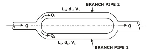
For Parallel pipes:
(i). Total discharge: Q = Q1 + Q2
(ii). The loss of head in each parallel pipe is the same.
i.e. Loss of head for branch pipe 1 = Loss of head for branch pipe 2
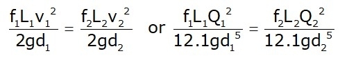
where: hf,1 and hf,2 are head loss at 1 and 2 respectively.
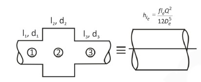
Equivalent Pipe: A compound pipe that consists of several pipes of different lengths and diameters to be replaced by a pipe having a uniform diameter and the same length as that of a compound pipe is called an equivalent pipe.
(i). Series connection:
![]()
![]()
(where: L = L1 + L2 + L3)
If f = f1 = f2 = f3
Then: 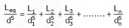
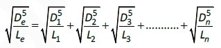
(ii). Equivalent length for parallel connection:
Hydraulic Gradient Line (HGL) and Total Energy Line (TEL):
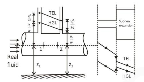
HGL → It joins a piezometric head ![]() at various points.
at various points.
TEL → It joins the total energy head at various points

Note:
1. HGL is always parallel but lower than TEL by velocity head.
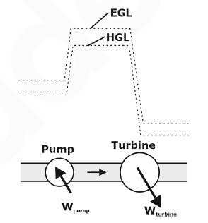
2. For stationary bodies such as reservoirs or lakes, the EGL and HGL coincide with the free surface of the liquid.
3. A steep jump or droop occurs in EGL and HGL whenever mechanical energy is added to the fluid (by a pump or mechanical energy is removed from the fluid (by a turbine) respectively.
Power Transmission through Pipe (P):
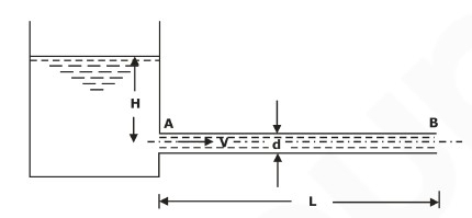
Pideal = ρQgH
Pideal = ρQg(H-hf)
hf = head loss
For maximum efficiency: ![]()
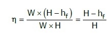
Power delivered by a given pipeline is maximum when the flow is such that one-third of the static head is consumed in pipe friction. Thus, efficiency is limited to only 66.66%
Maximum efficiency, ![]()
Water Hammer: When a liquid is flowing through a long pipe fitted with a valve at the end of the pipe and the valve is closed suddenly a pressure wave of high intensity is produced behind the valve. This pressure wave of high intensity is having the effect of hammering action on the walls of the pipe. This phenomenon is known as the water hammer.
The intensity of pressure rise due to the water hammer,
![]()
When the valve is closed gradually when the valve closed suddenly with a rigid pipe
![]()
When the valve closed suddenly with a plastic pipe

If the time required to close the valve
![]() Valve closure is said to be gradual.
Valve closure is said to be gradual.
![]() The valve closure is said to be sudden.
The valve closure is said to be sudden.
Where, L = Length of pipe
D = Diameter of pipe
C = Velocity of pressure wave produced due to water hammer ![]()
v = Velocity of flow
K = Bulk modulus of water
E = Modulus of elasticity for pipe material.
t = Time required to choose the valve.
This topic is important for GATE ME, ISRO ME, ESE IES ME, and other Mechanical exams.
If you aiming to crack GATE & ESE, Other PSU Exams then you must try Online Classroom Program to get unlimited access to all the live structured courses and unlimited mock tests from the following links:
ESE and GATE ME Online Classroom Program (24+ LIVE Courses and 160+ Mock Tests)
Click on the Links Below to Avail Test Series:
Click Here to Avail GATE/ESE ME Test Series !!! (150+ Mock Tests)
Thanks
BUJU’S EXAM PREP
DREAM STRIVE SUCCEED
Get complete information about the GATE exam pattern, cut-off, and all those related things on the Byju Exam Prep official youtube channel.


