- Home/
- GATE ELECTRONICS/
- GATE EC/
- Article
Multivibrator – Definition, Diagram, Implementation & Applications
By BYJU'S Exam Prep
Updated on: September 25th, 2023

A multivibrator is a very important and commonly used pulse-shaping and generator circuit in applying digital and electronic systems. The term multi-vibrator refers to the oscillating response of a pulse generator circuit. For example, multivibrators are often used as a register or flip-flop, and the generated harmonic waves can be used as clock pulse signals for driving digital sequential circuits.
Any multivibrator’s overall working consists of switch transistors, capacitors’ charging and discharging, and resistors. We can achieve the generated pulse signal’s time period, frequency, and waveform by analyzing the aspects of a multivibrator circuit. We will start with the basic definition of a multivibrator, follow along with its different types, and briefly discuss their implementations.
Download Digital circuits Short Notes PDF
Download Formulas for GATE Electronics & Communication Engineering – Control System
Table of content
What is a Multivibrator?
A multivibrator is used to produce oscillations of different duty cycles, and they are commonly used for clock signal generation in digital circuits. It has two output levels, High and Low, and the duty cycle is determined from the period of these states; a wave having the same On and OFF time means a 50% duty cycle.
Note: The duty cycle of a wave is given by: TDuty = TON/(TON+TOFF)
Download Analog Circuits Short Notes PDF
Download Formulas for GATE Electronics & Communication Engineering – Digital Circuits
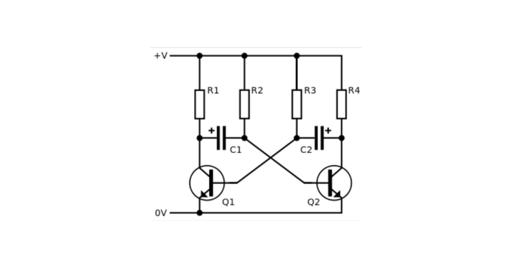
Multivibrator Circuit Diagram
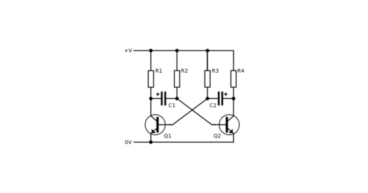
Figure: Typical Multivibrator
Multivibrator Applications
There are various applications of multivibrators; a few are wave and pulse generators, Frequency dividers, common frequency sources used in radar and tv circuits, saw-tooth generators etc.
Download Formulas for GATE Electronics & Communication Engineering – Electronic Devices
Different States in a Multivibrator
There are two states in a multivibrator:
- Stable State
- Quasi-Stable State
Stable State
A stable state means the wave will continue to follow its current state until disturbed by an external source.
- In a bistable, the state of the wave is ON after having an input at T1, and it continues to be the same until another input is given at T2.
- In monostable, the state of the wave returns to its original state or the stable state after some time from the application of input at T1.
Quasi-Stable State
A quasi-stable state means the wave can not stay in the state at all times and will return to a stable state or keep fluctuating between the quasi-stable states.
- In Monostable, High is the quasi-stable state, and Low is the stable state. After applying an input, the wave switched to the quasi-state and returned to a stable state without needing external help.
- In Astable, there are no stable states; hence once the device starts, it continues to fluctuate between its quasi-stable states.
Multivibrator Types
Three types of the multivibrator are:
- Astable
- Monostable
- Bistable
Astable
An Astable does not have stable states and only has two quasi-stable states. It can be constructed with different elements and configurations; however, the capacitors and resistors will still be present for the charging-discharging action and setting up the duty cycle.
Monostable
It only has one stable state and one quasi-stable state. It is also referred to as On-shot or Single-shot because it returns to the stable state after a fluctuation induced by the applied input. An external pulse is required to change the state from stable to quasi-stable.
Bistable
It has two stable states and continues to follow the present state until the next input is applied. For this reason, it is also used as a storing element since it can store a value High or Low state and can be changed when a different value state needs to be saved by applying an input trigger. Therefore, there is no sense in writing the period for a bistable because we know the state is on hold for an indefinite time, i.e., until the next input pulse is applied. However, we will still see different circuits for it.
Implementation of Multivibrator Using BJT
Astable
There is no need to apply any input trigger in an astable, and we can take the output from the collector terminal of any of the two transistors.
- On-time of transistor Q1: t1=0.693R2C1(also the time for Q2 OFF)
- Off-time of transistor Q1: t2=0.693 R3C2 (also the time for Q1 ON)
- The total time period of the rectangular pulse wave generated is:
T= t1+t2=0.693R2C1+0.693 R3C2
Monostable
We need to provide a positive trigger in a monostable, and the output is taken from the second transistor.
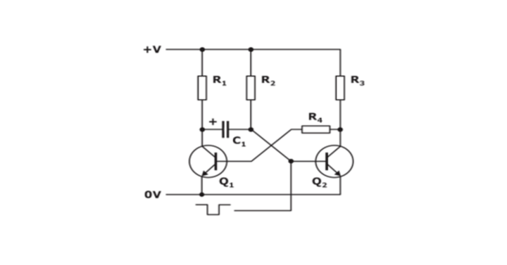
- The ON time or the time for which the circuit will be in a quasi-stable state is:
T=0.693 R1C
Bistable
We need to provide a negative trigger pulse to set the output high or low for a bistable. Suppose we apply a negative trigger in Q1; this will set output 1 as high. We need to provide another negative trigger in Q2 again to set it to Low. We can choose any of the two transistors to get the output, which can also be backed by seeing the symmetrical nature of the circuit.

Implementation of Multivibrators Using Op-amp
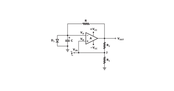
Astable
No intentional trigger is required, and the circuit will oscillate between the On and Off states depending on the charging and discharging action of the capacitor.

- Feedback factor β = R1/R1+R2
- Time required for the capacitor to charge: t1 = RfC ln(1+β/1-β)
- Time required for the capacitor to discharge: t2 = RfC ln(1+β/1-β)
- The total time period of the rectangular pulse wave generated is:
T=2RfC ln(1+β/1-β)
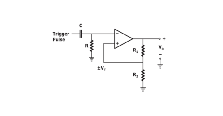
Monostable
A negative trigger pulse is fed to the non-inverting input of the op-amp to set the circuit in a quasi-stable state.
- The ON time or the time for which the circuit will be in a quasi-stable state is:
T=2RC ln(1+R1/R2)
Bistable
A positive edge trigger is required to set the output low, and a negative trigger pulse is required to set the output high.
Implementation of Multivibrators using Timer IC-555
Astable
The pin connections and circuitry for an astable multivibrator are shown below.
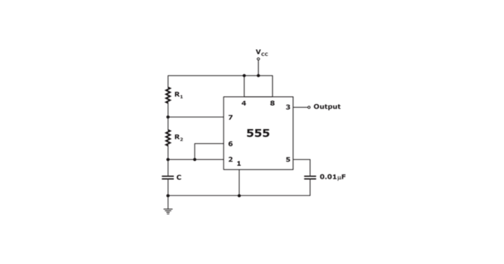
- Capacitor charging time/ Wave High time THIGH=0.693(R1+R2)C
- Capacitor discharging time/ Wave Low time TLOW=0.693 R2C
- The total time period of the rectangular pulse wave generated is:
T=THIGH+TLOW
Monostable
The pin connections and circuitry for a bistable multivibrator are shown below.
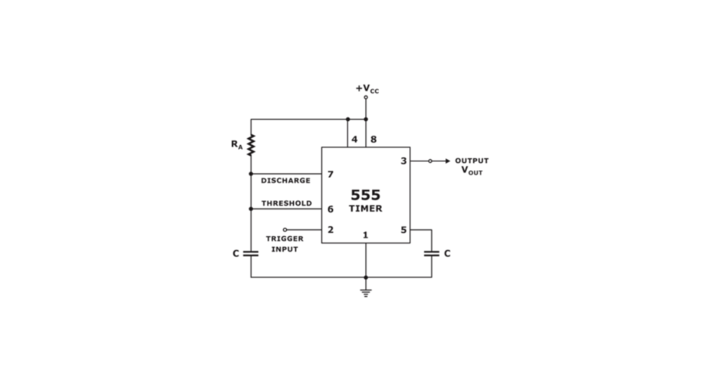
- The ON time or the time for which the circuit will be in a quasi-stable state is:
T=1.1 RAC
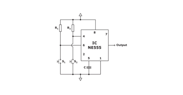
Bistable
The pin connections and circuitry for a bistable multivibrator are shown below. The operation of the circuit is controlled by two switches, where switch S1 is for SET and S2 is for RESET.