
- Home/
- GATE MECHANICAL/
- GATE ME/
- Article
Design for Static and Dynamic Loading Notes for GATE and Mechanical Engineering Exams
By BYJU'S Exam Prep
Updated on: September 25th, 2023

Static load: A static load is gradually applied to a mechanical component whose magnitude or direction is independent of the time.
Modes of failure: A mechanical component failure may be the result of any one of the following failure modes:
Table of content
-
1.
Strength or Failure Stress

-
2.
Types of Materials:
-
3.
Torsional Shear Stress
-
4.
Bending Stresses in Beams
-
5.
Combined Bending and Torsion
-
6.
Comprehensive Preparation for GATE & ESE ME Exams(500+ Hours of Live Classes, 300+ Quizzes for Practice and 60+ Mock Tests)
-
7.
Get Unlimited Access to all 161+ Mock Tests
Static load: A static load is gradually applied to a mechanical component whose magnitude or direction are independent of the time.
Modes of failure: A mechanical component failure may be result of any one of the following failure modes:
(i). Failure by elastic deflection
(ii). Failure by general yielding
(iii). Failure by fracture
Stress: Stress is defined as an intensity or magnitude of an internal resisting force developed at a point under given load.![]()
Strength or Failure Stress
- Strength is defined as the maximum or limiting value of stress that a material can withstand without any failure or fracture.
- If σinduced ≤ σyield, then yielding, then yielding (permanent deformation) will not occur.
- If σinduced ≤ σultimate, then fracture will not occur.
- If σyield ≤ σinduced ≤ σultimate, then yielding will occur without any failure.
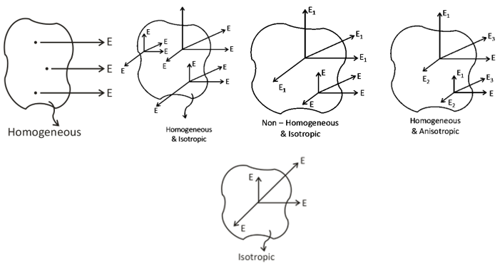
Types of Materials:
(a). Homogenous material: Same elastic properties at any point in a given directions [i.e., elastic properties are independent of point].
(b). Isotropic Material: Same elastic properties in any direction at a given point [independent of direction].
(c). Anisotropic Material: Exhibit direction dependent elastic property.
(d). Orthotropic Material: Exhibits different elastic properties in orthogonal directions at a given point.
Shear Stress: If the external force on a component in applied in such a way that it tends to slide the adjacent planes relative to each other, then resulting stresses induced are called shear stresses.
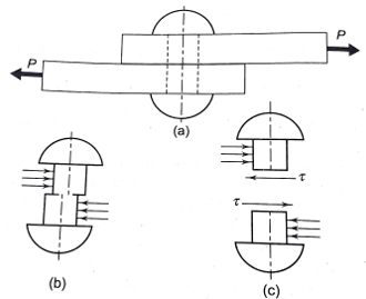
Fig.1: Shear failure of mechanical member
![]()
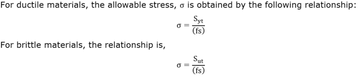
Factor of safety (FOS): It should be kept in mind while designing a component that it should have sufficient excessive strength to prevent any failure due to the accident. Thus, it is obtained by considering a suitable factor of safety (FOS).
The factor of safety is defined as:
![]()
The allowable stress is the actual stress value considered for determining the dimensions of the component during the design phase. The designer expects that the applied stress on the component will not go beyound allowable stress under normal operating conditions.
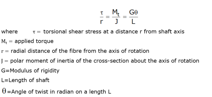
Torsional Shear Stress
- A component subjected to the two equal and opposite couples acting in parallel planes, is called under torsion and the internal stresses produced to resist the applied stresses are called torsional shear stresses.
- The torsional shear stress is maximum at the outer surface while it is zero at the centroidal axis.
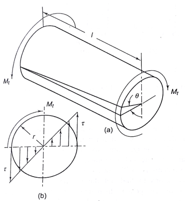
Fig.2: Shaft subjected to torsion
The torsion equation is given as:
Design of shaft: The design of the shaft can be done on the basis of two criteria which are explained below:
(a). Strength Criteria: The strength criteria uses the first two terms of torsion equation and design is done on basis that stress induced in the shaft must not exceed the strength of material of shaft.
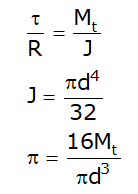
(b). Rigidity criteria: The rigidity criteria uses the last two terms of torsion equation and design is done on the basis that maximum angular twist must exceed a certain value.
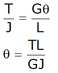
The expression GJ is called torsional rigidity of the shaft.
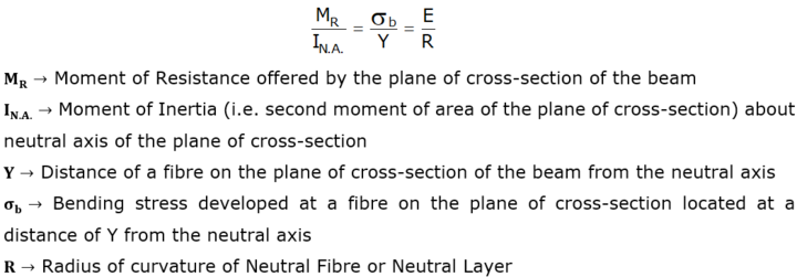
Bending Stresses in Beams
A beam or a member is said to be under pure bending when it is subjected to two equal and opposite couples in a plane along the longitudinal axis of the beam (i.e. bending couples) in such a way that magnitude of bending moment remains constant throughout the length of the beam.
Bending equation: The following equation is known as bending equation.
Combined Bending and Torsion
- Mechanical members are generally subjected to more than one kind of loads at a time. These loads may be axial loads, bending loads or/and torsional shear loads etc. Transmission shafts are often subjected to axial tensile force, bending moment or torsional moment or their combinations.
- The design of transmission shaft consists of determining the correct shaft diameter from strength and rigidity criterion.
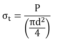
- When the shaft is subjected to axial tensile force (P), the tensile stress is given by:
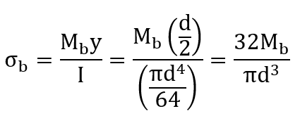
- When the shaft is subjected to pure bending moment (Mb), the bending stresses are given by:
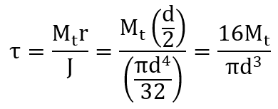
- When the shaft is subjected to pure torsional moment (Mt), the torsional shear stress is given by:
- When the shaft is subjected to combination of loads, the principal stresses and principal shear stresses developed in the shaft are obtained by constructing Mohr’s Circle.
- The normal stress is denoted by σx while the shear stress is denoted by τ .
Two cases are considered for calculating σx:
Case I: The shaft is subjected to a combination of axial force, bending moment and torsional moment: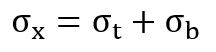
Case II: The shaft is subjected to a combination of bending and torsional moments without any axial force: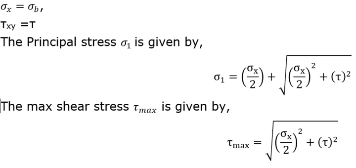
If you are preparing for ESE/ GATE or other PSU Exams (Mechanical Engineering), then avail Online Classroom Program for ESE and GATE ME:
Comprehensive Preparation for GATE & ESE ME Exams(500+ Hours of Live Classes, 300+ Quizzes for Practice and 60+ Mock Tests)
You can avail Test Series specially designed for all Mechanical Engineering Exams:
Get Unlimited Access to all 161+ Mock Tests
All the Best!
#DreamStriveSucceed.
Update BYJU’S Exam Prep, Best GATE exam app for Preparation


