
What is Photogrammetry? Definition, Overlap, Types
By BYJU'S Exam Prep
Updated on: September 25th, 2023

Photogrammetry is the branch of science in which photos are taken, and these are used to understand the different features of the ground. In civil engineering, the topic of photogrammetry is covered in the surveying subject. This topic is very helpful for competitive examinations like GATE and ESE.
Photogrammetry PDF
Photogrammetry can be classified into different types based on where the photographs are taken. If photographs are taken from near the ground, it is called terrestrial photogrammetry; if it is taken with the camera mounted on the aircraft above the ground, it is called aerial photogrammetry. This article contains basic notes on the “Photogrammetry” topic of the “Surveying” subject.
Table of content
What is Photogrammetry?
Photogrammetry is a part of surveying used to obtain relevant information on the ground with the help of photos taken from near or above the ground. Different ground features, the topography of the ground, objects on the ground, etc., can be obtained with the help of photogrammetry. And it is also important to the GATE exam.
In photogrammetry, different photos are taken with overlaps between them at a particular scale. Different features on the ground are estimated based on the selected scale of the photographs. The scale of the photographs depends on whether it is taken in a vertical or tilted position. These are explained below:
- Scale of a Vertical Photograph
Scale, S = Map distance/ Ground distance ⇒ f/(H-h)
Where,
- H = height of the exposure station (or the airplane) above the mean sea level.
- h = Height of ground above MSL
- f = Focal length of the camera
If A and B are two points on the ground having elevations ha and hb above MSL, then the Average scale of a line joining A and B is given by.
S = f/[H-{(ha + hb)/2}]; where (ha + hb)/2 = havg
- Datum scale
S = f/H
- Scale of a photograph
Sh = l/L
where
- l = distance in the photograph
- L = distance in the ground.
Computation of the line length between points of different elevations from measurement on a vertical photograph.
If A and B be two ground points having elevations ha and hb above MSL and coordinates (Xa, Ya) and (Xb, Yb)
Let a and b be the position of corresponding points in the photograph and (xa, ya) and (xb, yb) be the corresponding coordinates.
then,
xa/Xa = ya/Ya =f/(H – ha)
xb/Xb = yb/Yb =f/(H – hb)
where,
- Xa = (H – ha)xa/f
- Xb = (H – hb)xb/f
- Ya = (H – ha)ya/f
- Yb = (H – hb)yb/f
The length between AB is given by
L = [(Xa – Xb)2 + (Ya – Yb)2]0.5
- Relief displacement on a Vertical Photograph
When the ground is not horizontal, the scale of the photograph varies from point to point. The ground relief is shown in perspective in the photograph. Therefore, every point on the Photograph is displaced from the true orthography position. This displacement is called relief displacement.
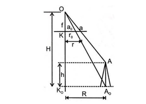
r = Ka
r0 = Ka0
R = K0A0
aa0 is called relief displacement.
aa0 = r – ro
from a similar triangle
r/R = f/(H-h) ⇒ r = fR/(H-h) …(i)
r0/R = r/H ⇒ r0 = fR/H …(ii)
So relief displacement


So relief displacement
![]()
If relief displacement is known, then the height of an object is given by,
h = dH/R
The scale of a tilted photograph

where,
![]()
- θ = 180-s
- s = Swing
- t = tilt
- f = Focal length
- H = Flying height above datum
- h = height of ground above datum.
It can be seen that the tilt and relief displacements tend to cancel in the upper part of the photograph while they are cumulative in the lower part.
Important Definitions in Photogrammetry
(i) Camera Axis: Line passing through the center of the camera lens perpendicular both to the camera plate (Negative) and picture plane (photograph).

(ii) Picture Plane: A positive plane perpendicular to the camera axis.
(iii) Principal point: K or K’ point on the intersection of the camera axis with either the picture plane or the camera plate.
(iv) Focal length (f): Perpendicular distance from the center of a camera lens to either to picture plane or camera plate. It satisfies the relation.
![]()
(v) Nodal point: Nodal point is either of two points on the optical axis of a lens so located that when all object distances are measured from one point, all image distances are measured from another. They satisfy the simple lens relation.
(1/f) = (1/u) + (1/v)
(vi) Principal plane: It is a plane that contains a principal line and optical axis.
(Vii) Oblique photograph: Photographs taken from the air with the axis of the camera tilted vertically is called oblique photographs; these are of two types
- Low Oblique photograph: An oblique photograph that does not show the horizon is called a low oblique photograph.
- High Oblique photograph: If the tilt is more up to such that horizon is shown, it is called a high oblique photograph.
(viii) Convergent photograph: Low oblique photographs which are taken with two cameras exposed simultaneously at successive exposure stations, with their axes tilted at a fixed inclination from vertical so that forward exposure of the first station from a stereo pair with backward exposure of the next station, these photographs are called convergent Photographs.
Overlap in the Photographs
There are two types of overlaps in Photographs. These overlaps are essential for the GATE CE question paper. The two important overlaps are:
- Longitudinal overlap = 55 to 65%
- Lateral Overlap = 15 to 35%
For the maximum rectangular area to be covered by one photograph, the rectangle should have the dimension in the flight to be one-half the dimension normal to the direction of flight.
W = 2BW = 1.22H W = width of ground % overlap ≈ 60% in the longitudinal direction.
Number of Photographs to Cover a Given Area
N = A/a
A = Total area considered in the photogrammetry
a = net ground area covered by each photograph
N = number of photographs required.
a = L×W
L = (1-Pl)s.l.
W = (1-Pw)s.l.
a = l.ws2(1-Pl)(1-Pw)
where
- l = length of photographs in the direction of flight
- W = width of a photograph.
- Pl = % lap in the longitudinal direction
- Pw = lap in the longitudinal direction
- S = Scale of Photograph
If instead of total area A, the rectangular dimensions L1 × L2 (parallel and Transverse to flight) are given, then the number of photographs required is given as follows.
Let
- L1 = Dimension of area parallel to the direction of flight
- L2 = Dimension of area Transverse the direction of flight
- N1 = Number of photographs in each strip
- N2 = Number of strips required.
- N = Total number of photographs to cover the whole area.

- Interval between exposures
T = 3600 L/V
V = ground speed of the airplane in kmph.
L = ground distance covered by each photograph in the direction of flight = (1 – Pl) s.l …… in Km
Types of Photogrammetry
Two types of photogrammetry play a vital role in the GATE CE exam are listed below:
(i) Terrestrial photogrammetry: Photographs are taken from a fixed position on or near the ground.
(ii) Aerial Photogrammetry: Photographs are taken from a camera mounted in an aircraft flying over the area.
Phototheodolite: It is a combination of “theodolite and a terrestrial camera. Important parts are:
- Camera Box of a fixed focus type.
- The hollow rectangular frame consists of two crosshairs.
- Photographic plate
- Theodolite
Horizontal and Vertical Angles From the Terrestrial Photograph


Angle φ1 is the magnetic bearing of the camera axis (or principal vertical plane.)
Azimuth of line Ok = φ1
The azimuth of line OA = φ1 – αa (OA is left to OK)
Azimuth of line OB = φ1 – αb (OA is right to OK)
So, Azimuth of a line = Camera azimuth + α
Elevation of a point by photographic measurement
Consider Point A

If V = Elevation of point A above the Horizontal plane through the camera axis.
From Similar triangle

Elevation of point A.
h = HC + V + C

Where,
- HC = Elevation of camera
- V = Elevation of point A
- C = Correction for curvature and refraction.
h = HC + V + C
- Determination of the focal length of the lens
Take two points, A and B. Measure angle θ very accurately from a theodolite.


Quadratic equation in f.

What is Aerial Photogrammetry?
Aerial photogrammetry is a type of photogrammetry in which an aerial photograph is taken with a fast-speed aerial camera with a very high speed and efficient shutter, using high-speed emulsion for the film.
Important Definitions in Aerial Photogrammetry
- Vertical photographs: When a photograph is taken keeping the camera axis vertical, coinciding with the direction of gravity, it is called a vertical photograph.
- Tilted Photograph: camera axis inclined at an angle from vertical.
- Exposure station: Point in space occupied by the camera lens at the time of exposure.
- Flying height: Elevation exposure station above sea level.
- Flight line: A line drawn on the map represents the aircraft’s track.
- Focal length: distance from the front Nodal point of the lens to the plane of the photograph (OK)
- Principal Point: The point where the perpendicular dropped from the front nodal point strikes the photograph (K).
- Nadir Point: Nadir point is a point where the plumb line intersects the photograph.
- Ground Nadir point: Point vertically beneath the exposure station (Point N).
- Tilt: Vertical angle defined by the intersection at the exposure station. ∠KON = t = tilt
- Principal Plane: Plane defined by lens (O) ground Nadir Point (N) Principal point produced on the ground (K).
- Principal Line: Intersection of the principal plane with the plane of the photograph (line NK)
- Isocentre: Isocentre is the point at which the bisector of the angle of tilt meets the photograph.
- Swing: Angle measured in-plane of a photograph from + y-axis clockwise to Nadir point.
- The azimuth of the principal plane: Clockwise horizontal angle measured about the ground nadir point from the ground survey north meridian to the principal plane of the photograph.
- Horizon point (h): Intersection of the principal line with the horizontal line through the perspective center. Such as, point h in the figure is the horizon point.
- Axis of Tilt: Axis of tilt is a line in the photograph plane perpendicular to the principal line at the isocentre, such as i1, i2 in the figure. The plane of the photograph is tilted about the axis.

Relation between principal point, plumb point, and isocentre
(i) NK = distance of nadir point from principal point.
NK/Ko = tan t ⇒ NK = Ko tan t = f tan t
(ii) Ki = distance of the isocentre from the principal point.
(Ki/KO) = tan(t/2) ⇒ Ki = Ko tan(t/2)
(iii) Kh = distance of a principal point to a horizon point.
Kh = Ko cot t
Kh = f cot t


