- Home/
- GATE ELECTRONICS/
- GATE EC/
- Article
Feedback Amplifier
By BYJU'S Exam Prep
Updated on: September 25th, 2023

Feedback Amplifiers are designed to use feedback for better output production. A part of the output is taken as feedback and used as input to minimise the losses. An amplifier is a device that amplifies the signal applied to its input. However, an amplifier strengthens the input signal, regardless of whether it contains information or noise at the input. Because of this, the output of an amplifier tends to produce an amplified version of both noise and signal at the output, which is undesirable, so we mostly use feedback amplifiers to reduce the noise and stabilise the system.
Feedback amplifiers greatly reduce the effect of noise in an amplifier; negative feedback feeds the output back to the input with phase reversal. The article elaborates on types of feedback amplifiers, feedbacks in amplifiers and other topologies of amplifiers.
Table of content
What is Feedback Amplifier?
Feedback means connecting the output back to the input. Typically, a feedback amplifier has two sections. They are the feedback circuit and the amplifier. Resistors make up the feedback circuit. The purpose of the feedback circuit is to return a fraction of the output signal to the input.
Block Diagram of Feedback Amplifier
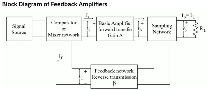
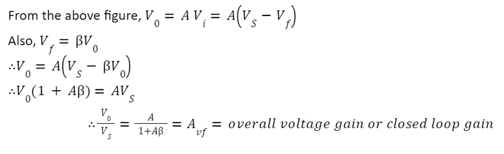
In the above figure, the ratio of output voltage Vo to the input voltage Vi is known as the amplifier’s gain and is denoted by A. The feedback network measures or samples the output signal Vo. Negative feedback in the amplifier reduces the signal that appears at the input of the basic amplifier. In contrast, positive feedback in the amplifier increases the signal that appears at the input of the basic amplifier. The signal source has voltage Vs. is known as the feedback ratio.
Aβ is the amplifier’s loop gain and the feedback amplifier’s most important characteristic parameter.
- The sign of Aβ determines the polarity of feedback. The loop gain must be positive for the feedback to be negative.
- The magnitude of Aβ determines the amount of feedback.
Types of Feedback Amplifiers
Feedback amplifiers can be classified in four ways based on the nature of the input (Voltage or Current) and the nature of output (voltage or current). Depending on the feedback amplifier to be used, one of the four types of feedback structures can be used.
- Voltage Series Feedback (Series-Shunt) or Voltage Amplifier
- Current Shunt Feedback (Shunt-Series) or Current Amplifier
- Current Series Feedback (Series-Series) or Transconductance Amplifier
- Voltage Shunt Feedback (Shunt-Shunt) or Transresistance Amplifier
Series refers to connecting the feedback signal with the input signal in a series connection. Similarly, the shunt connects the feedback signal with the input signal in parallel.
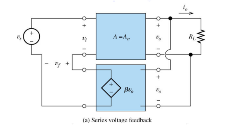
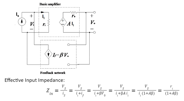
Voltage Series Feedback (Series-Shunt) or Voltage Amplifier
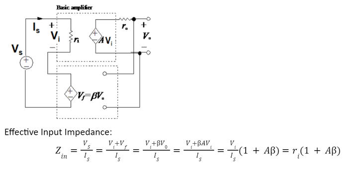
In voltage series feedback, a fraction of output voltage is sampled in the shunt and mixed with the input voltage in series. This feedback works as a voltage-controlled voltage source. The voltage series feedback amplifier can be represented as:
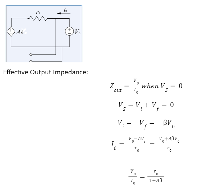
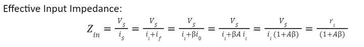
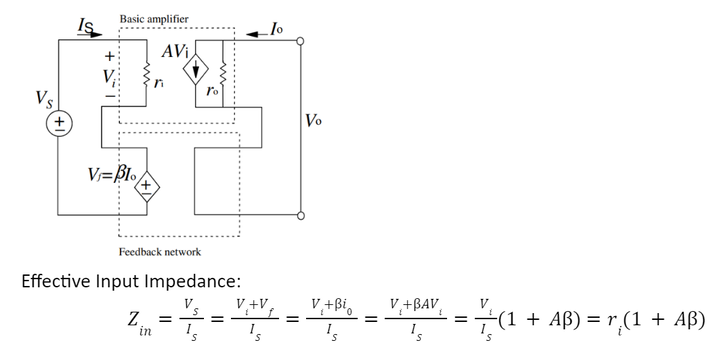
In this type of Feedback Amplifier, at the input, the amplifier and the feedback are connected in series so that the effective input impedance will increase. Similarly, at the output, the amplifier and the feedback are connected in a shunt so that effective output impedance will decrease.
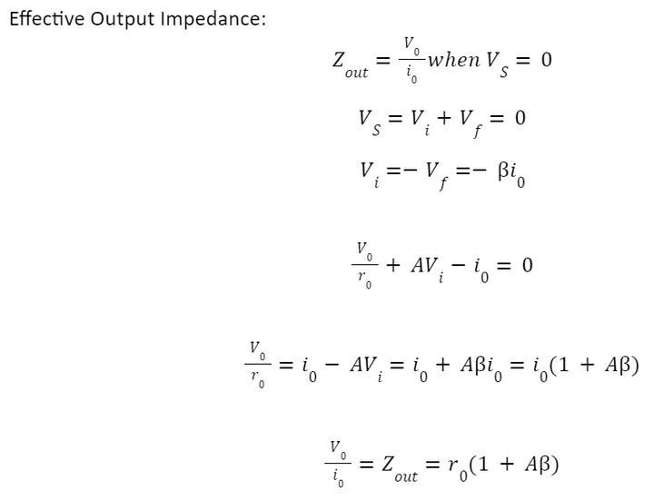
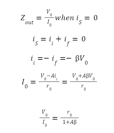
To calculate the effective output impedance, all the independent voltage or current sources should be deactivated.
Current Shunt Feedback (Shunt-Series) or Current Amplifier
In current shunt feedback, a fraction of the output current is sampled in series and mixed with the input current in the shunt. This feedback works as a current controlled current source. The current shunt feedback amplifier can be represented as:
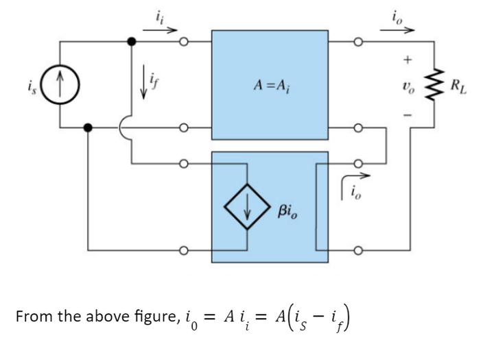
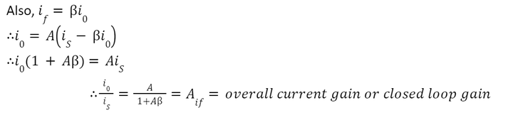
In this Feedback Amplifier, at the input, the amplifier and the feedback are connected in a shunt, so the effective input impedance will decrease. Similarly, the amplifier and the feedback are connected in series at the output, so effective output impedance will increase.
To calculate the effective output impedance, all the independent voltage or current sources should be deactivated.
Current Series Feedback (Series-Series) or Transconductance Amplifier
In current series feedback, a fraction of output current is sampled in series and mixed with the input voltage in the shunt. This feedback works as a voltage-controlled current source. The current series feedback amplifier can be represented as:
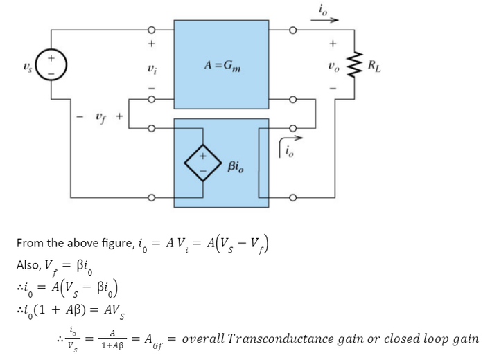
In this type of feedback amplifier, both at the input and output, the amplifier and the feedback are connected in series, so the effective input impedance and effective output impedance will be increased.
To calculate the effective output impedance, all the independent voltage or current sources should be deactivated.
Voltage Shunt Feedback (Shunt-Shunt) or Transresistance Amplifier
In voltage shunt feedback, a fraction of output voltage is sampled in the shunt and mixed with the input current in the shunt. This feedback works as a current-controlled voltage source. The voltage shunt feedback amplifier can be represented as:
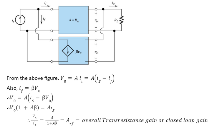
In this type of feedback amplifier, both at the input and output, the amplifier and the feedback are connected in a shunt, so the effective input impedance and effective output impedance will be decreased.
To calculate the effective output impedance, all the independent voltage or current sources should be deactivated.
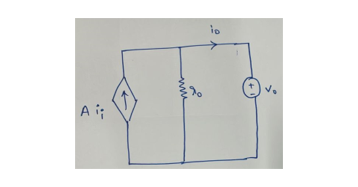
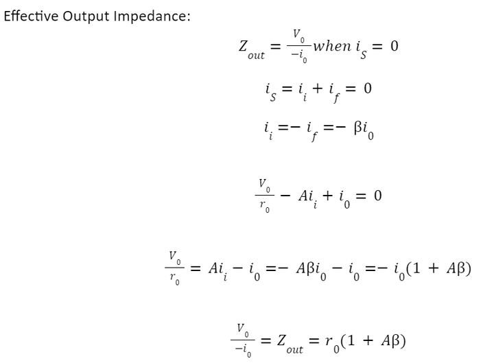
Effective Output Impedance:
Types of Feedback in Amplifiers
With the help of feedback in amplifiers, the amplifiers can be made stable, and the effect of noise can be reduced. Feedback can be either negative or positive, depending on whether the feedback signal supports or opposes the input signal.
- Negative Feedback in Amplifiers
- Positive Feedback in Amplifiers
Negative Feedback in Amplifiers
The amplifier in negative feedback introduces a 180° phase shift into the circuit. As a result, the input signal Vin and the resulting feedback voltage Vf are 180 degrees out of phase. Negative feedback in amplifiers has many benefits, including
- Gain is reduced by a factor of 1+Aβ in negative feedback, so stability is increased.
- Reducing overall distortion
- Decrease in noise
- Input impedance increased by the factor of 1+Aβ.
- Output impedance decreased by the factor of 1+Aβ.
The basic idea of the negative feedback in an amplifier is to trade off gain for other desirable properties. In amplifier design, negative feedback is preferred to affect one or more of the following goals:
- Desensitize the gain: to make the gain’s value less sensitive to variations due to the circuit components as they get affected by the change in temperature.
- Reducing non-linear distortion: to make the output proportional to the input.
- Decrease in noise: minimize the output generated by the unwanted input signals or by the circuit components themselves.
- Control input and output impedances.
- Extend the bandwidth of the amplifier.
Positive Feedback in Amplifiers
In positive feedback, for the feedback signal to be in phase with the input signal, both the input signal and feedback signal induce a 180° phase change, resulting in a 360° phase shift around the loop. It has drawbacks like
- Increasing overall distortion
- Gain stability is decreased.
Positive feedback is not suggested for amplifiers due to these drawbacks. If the positive feedback is more dominant in the circuit, it will result in oscillations and make the system unstable. However, these are the building blocks for oscillator circuits.
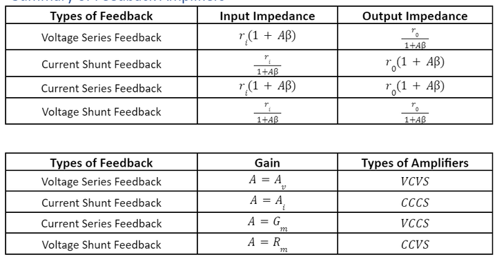
Summary of Feedback Amplifiers