- Home/
- GATE ELECTRONICS/
- GATE EC/
- Article
Clamping Circuit – Definition, Unbiased and Biased Clampers
By BYJU'S Exam Prep
Updated on: September 25th, 2023

The clamping circuit plays a vital role in shifting the original signal to some level on the y-axis or amplitude axis. Based on the requirement, we will use the respective clamping circuit. The p-n junction diodes are having a lot of applications. Clampers are one among them. In this article, get an overview of the clamping circuit and its classification.
In some applications, we must shift the original signal vertically on the amplitude axis. This process is known as clamping. So, accordingly, we will use the respective electronic circuit. By using a clipping circuit, we used to clip the part of the signal. But there won’t be any modification in the shape of the original signal at the output of the clamping circuit. Here we will see the clamping circuit diagram, definition, and types of clampers used in the clamping circuit in detail.
Table of content
What is a Clamping Circuit?
An electronic circuit is said to be a clamping circuit if it shifts the input signal to a level on the amplitude axis without a change in the shape of the signal. It is also known as clamper, in short. Since there is a shift in the amplitude level, we can call clampers Level shifters. We can use clamping circuits for any of the following operations.
- To place the positive peak or negative peak of the input signal at the required or desired level.
- To add the DC component to the input signal
- To subtract the DC component from the input signal.
Types of Clampers in Clamping Circuit
In this article, we are focusing on one of the important applications of Diodes. i.e., clampers. Here, we are assuming all the diodes that we use in the circuit diagrams are ideal. Clampers can be classified based on the direction (upwards / downwards) of shifting the signal and placing the diode in the circuit. Now, let us discuss the following types of clampers one by one.
- Unbiased Clampers
- Biased Clampers
Unbiased Clampers in Clamping Circuit
A clamper is said to be an unbiased clamper if there is no dc voltage source (bias) in series with the diode. It consists of mainly three components: diode, resistor, and capacitor. Based on the position of the diode, we can clamp the input signal on either the positive side or the negative side on the amplitude axis. Accordingly, we are having the following two types of unbiased clampers.
Positive Clamper
An unbiased clamper is said to be a positive clamper if it shifts the input signal towards the positive side on the amplitude axis. This circuit diagram along with the input-output waveforms is shown in the below figure. When a diode is in forwarding bias, there will be no output or zero output across the load resistor (RL). When the diode is in reverse bias, we will get the clamped version of the input signal across the load resistor (RL).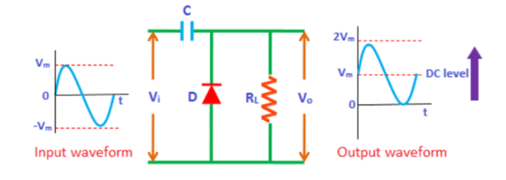
Negative Clamper
An unbiased clamper is said to be a negative clamper if it shifts the input signal towards the negative side on the amplitude axis. Just by reversing the Diode position, the positive clamper circuit becomes the negative clamper circuit. This circuit diagram along with the input-output waveforms are shown below figure.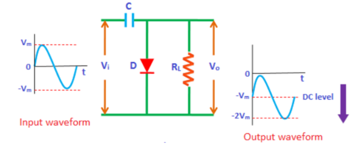
Biased Clampers in Clamping Circuit
If the DC shift obtained at the output by using unbiased clampers is not sufficient, then we must connect a dc voltage source (bias) accordingly in series with the diode. Then that circuit is known as a biased clamper. Based on the position of the diode and polarity of the dc voltage source (bias) we can clamp the input signal on either the positive side or negative side on the amplitude axis. Accordingly, we are having the following four types of biased clampers.
Positive Clamper with Positive Bias
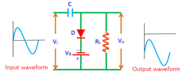
If we connect the positive terminal of the dc voltage source (bias) with the p-side of the p-n junction diode in the positive clamper circuit, then we will get the following circuit. It is known as a positive clamper with positive bias. The operation of this circuit is like that of a positive clamper. Because of the positive dc voltage (bias) present in the circuit, the output waveform got shifted upward (positive side).
Positive Clamper with Negative Bias
If we connect the negative terminal of the dc voltage source (bias) with the p-side of the p-n junction diode in the positive clamper circuit, then we will get the following circuit. It is known as a positive clamper with negative bias. The operation of this circuit is like that of a positive clamper. Because of the negative dc voltage (bias) present in the circuit, the output waveform got shifted downward (negative side).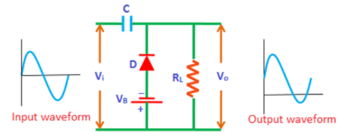
Negative Clamper with Positive Bias
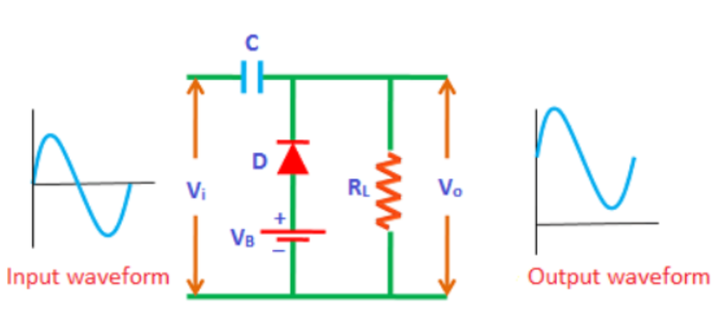
If we connect the positive terminal of the dc voltage source (bias) with the n-side of the p-n junction diode in the negative clamper circuit, then we will get the following circuit. It is known as negative clamper with positive bias. The operation of this circuit is like that of a negative clamper. Because of the positive dc voltage (bias) present in the circuit, the output waveform got shifted upward (positive side).
Negative Clamper with Negative Bias
If we connect the negative terminal of the dc voltage source (bias) with the n-side of the p-n junction diode in the negative clamper circuit, then we will get the following circuit. It is known as negative clamper with negative bias. The operation of this circuit is like that of a negative clamper. Because of the negative dc voltage (bias) present in the circuit, the output waveform got shifted downward (negative side).