Moment Distribution Method of Structural Analysis
By BYJU'S Exam Prep
Updated on: September 25th, 2023

The Moment Distribution Method is one of the two basic methods of structural analysis. The two methods of structural analysis are the displacement method/ equilibrium method and another one is the force method/ compatibility method. The moment distribution method is one of the displacement methods. The moment distribution method is used for statically indeterminate beams and frames.
The moment distribution method is one of the most widely practised methods. In this article, we will have a brief discussion on the displacement method and force method. We will discuss the moment distribution method in detail.
Download Formulas for GATE Civil Engineering – Environmental Engineering
Table of content
What is the Moment Distribution Method?
The moment distribution method is practical for analysing statically indeterminate beams and rigid frames. Every joint of the structure to be analysed is fixed in the moment distribution method to create fixed-end moments. Then, each fixed joint is released one by one, and the fixed-end moments (which are not in equilibrium at the time of release) are transferred to nearby members until equilibrium is attained. Furthermore, the moment distribution approach may be proved mathematically as the process of iteratively solving a set of simultaneous equations. Let us discuss the displacement method and force method.
Displacement Method
The displacement method is a method of structural analysis in which displacements are treated as unknowns. The number of unknowns in the displacement method is treated as equal to Kinematic Indeterminacy. Different displacement methods are Slope Deflection Method, Moment Distribution Method, and Kani’s Stiffness Matrix Method.
Force Method
The Force Method is a method of structural analysis in which redundant forces are treated as unknowns. The number of redundant forces is treated as equal to static indeterminacy. Flexibility matrix, consistent deformation, column analogy, and elastic centre are different force methods.
- The moment distribution method is a structural analysis method for statically indeterminate beams and frames developed by Hardy Cross.
- The method only accounts for flexural effects and ignores axial and shear effects.
- The moment distribution method falls into the displacement method of structural analysis.
- In the slope deflection method, the end moments are computed using the slopes and deflection at the ends. Contrarily in the moment distribution method, the slopes at the ends are made zero as a first step. This is done by fixing the joints.
In the moment distribution method, every joint of the structure to be analysed is fixed to develop the fixed-end moments. The moment distribution method in mathematical terms can be demonstrated as solving a set of simultaneous equations using iteration.
Download Formulas for GATE Civil Engineering – Structural Analysis
Important Points of Moment Distribution Method
- When the member is fixed at one end and a moment is applied at the other end, which is simply supported or hinged, the moment induced at the fixed end is one-half of the applied moment. The induced moment at the fixed end is in the same direction as the applied moment.
- If a moment is applied in a stiff joint of a structure, the moment is resisted by various members in proportion to their respective stiffnesses (i.e., a moment of inertia divided by the length).
- If the member’s stiffness is more, it resists more bending moments and absorbs a greater proportion of the applied moment.
- While distributing the moments in a rigid joint, if one end of the member is not restrained, then its stiffness should be multiplied by (3/4).
- In a fixed beam, if the support settles/subsides/sinks by an amount Δ, the moment required to make the ends horizontal is 6EIΔ/l2.
Structural Analysis Using Moment Distribution Method
Hardy Cross developed the moment distribution method. In the moment distribution method, displacements are treated as unknowns. The moment distribution method is also known as the equilibrium or displacement method. It is suitable for analyzing indeterminate structures like beams and rigid jointed frames.
In the moment distribution method, the acting axial forces and corresponding axial force deformations are neglected. The moment distribution method is applicable for both prismatic and non-prismatic members.
Download Formulas for GATE Civil Engineering – Geotechnical Engineering
Moment Distribution Method Formula
Various formulae and factors are used in the moment distribution method, which can help reach the results quickly. Check out the formulae of some important terms used in the analysis of the Moment Distribution Method.
Stiffness
Rotational stiffness can be defined as the moment required to rotate through a unit angle (radian) without translating either end.
k = F/Δ or M/θ
Where,
- K = Stiffness
- F = Force required to produce deflection Δ
- M = Moment required to produce rotation θ.
Stiffness Factor/ Rotational Stiffness
The Stiffness Factor is the moment required to produce a unit rotation.
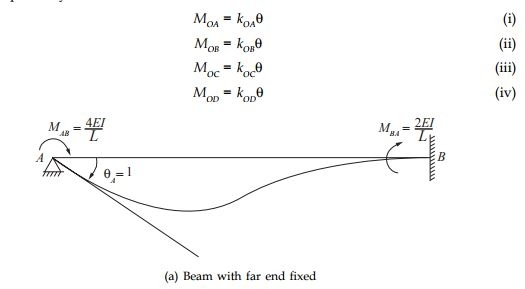
Case 1: Far end is fixed
M= 4EI/L
Case 2: Far end is hinged
M= 3EI/L
Case 3: Far end is free
M= 0
Case 4: Far end is a guided roller
M= EI/L
Carry Over Factor
Carry Over Factor is the ratio of the far-end moment and near-end moment. Carry Over Moment (COM) is also called a developed moment or induced moment. It is the moment developed at one end due to the moment at another end.

COF = COM/Applied Moment
Carry Over Factors for different cases are:
Case 1: When a far end is fixed
COF = ½
Case 2: One end is hinged
COF = 0
Case 3: Cantilever Beam
COF = -1
Case 4: Far-end is guided by roller
COF = -1
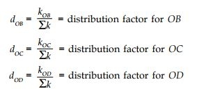
Distribution Factor

Consider a frame with members OA, OB, OC and OD rigidly connected at O, as shown below. Let M be the applied moment at joint O in the clockwise direction. Let the joint rotate through an angle θ. The members OA, OB, OC and OD also rotate by the same angle θ
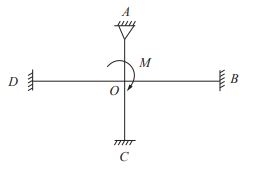
Let kOA, kOB, kOC and kOD be the stiffness values of the members OA, OB, OC and OD, respectively; then-
 Relative Stiffness
(i) When the farther end is fixed
Relative stiffness for member = l/L
(ii) When the farther end is hinged
Relative stiffness for member = 3l/4L
Sign Convention in Moment Distribution Method
Clockwise moments are considered positive and anticlockwise moments negative
- +ve → Sagging
- –ve → Hogging
- and All clockwise moment → +ve
- and All Anti clockwise moments → –ve
- The span length is l


Moment Distribution Method Example
Question 1. Find the stiffness factor or rotational stiffness at O.
Solution:
δ= 3EI/L+ 4EI/L+0+ EI/L
δ= 8EI/L
Question 2. Find the relative stiffness distribution factors of members.
Solution:
KAB=3EI/L
KAC=3EI
KAD=4EI/L
KAE=0
The distribution factor is the ratio in which the moment sharing capacity of various members meets at a rigid joint.
DF= K/∑K
(DF)AB= KAB/∑KA= 4/11
(DF)AC= KAC/∑KA= 3/11
(DF)AD= KAD/∑KA= 4/11
(DF)AE= KAE/∑KA= 0
Distribution factor at a rigid joint = 1
For fixed support, distribution factor = 0
For hinged or roller beam, distribution factor = 1
Question 3. Find stiffness of various elements.

Solution:
- Stiffness of OA = 4EI/L
- Stiffness of OB = 3EI/L
- Stiffness of OC = 3EI/L
- Stiffness of OD = 0
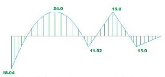
Question 4. Draw the bending moment diagram for the continuous beam ABCD loaded as shown below. The relative moment of inertia of each span of the beam is also shown in the figure.
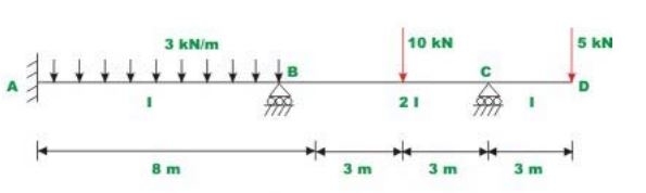
Solution:
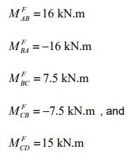
Note that joint C is hinged, so stiffness factor BC gets modified. Assuming that the supports are locked, calculate fixed end moments. They are
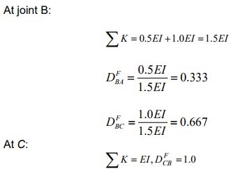
In the next step, calculate stiffness and distribution factors
KBA = 4EI/8
KBC = (3/4)(8EI/6)
KCB = 8EI/6
Now all the calculations are shown below
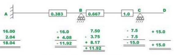
Computation