Truss: What is Truss, Types, Components, Truss in Civil Engineering
By BYJU'S Exam Prep
Updated on: September 25th, 2023

Truss allows us to create strong and durable structures while using materials efficiently and cost-effectively. A truss is a structure that consists of members assembled into connected triangles so that the overall assembly behaves as a single object. Trusses are most commonly used in bridges, roofs, and towers.
When the truss members lie essentially in a single plane, that type of truss is called a plane truss. When the members of the truss lie three-dimension, the truss is called a space truss. Trusses are made of triangular units constructed with straight members. The ends of these members are connected at joints. They can carry significant loads, transferring them to supporting structures.
Download Formulas for GATE Civil Engineering – Structural analysis
Table of content
-
1.
What is a Truss?
-
2.
Types of Truss
-
3.
What is a Perfect, Imperfect, and Redundant Truss?
-
4.
Types of Truss Based on Determinacy
-
5.
Statically Determinate Truss
-
6.
Statically Indeterminate Truss
-
7.
Zero Force Members
-
8.
Assumptions in Truss Analysis
-
9.
Sign Convention and Graphical Representation of Internal Forces
-
10.
Method of Truss Analysis
-
11.
Methods of Joints
-
12.
Method of Section
What is a Truss?
A truss is a structure that consists of straight members arranged into connected triangles so that the whole assembly forms a stable structure. In a truss, the straight members are connected at joints called nodes, and all the forces and reactions are assumed to act only at these nodes. Consequently, the truss members are subjected to axial loads (tensile and compressive) without bending.
A truss is statically determinate when all its member forces can be calculated using only equilibrium equations. Otherwise, it is statically indeterminate.
Download Formulas for GATE Civil Engineering – Fluid Mechanics
Types of Truss
There are various types of trusses. Different designs carry loads in different ways. The members of these trusses are located in the same plane, these are called Planar Trusses, and we can analyze them as Two – Dimensional structures. Following are the various types of trusses:-
- Fink Roof Truss
- Fan Roof Truss
- King Post Truss
- Howe Roof Truss
- Pratt Roof Truss
- Modified Queen Roof Truss
- Howe Bridge Truss
- Pratt Bridge Truss
- Warren Bridge Truss
- Parker Bridge Truss
- Baltimore Bridge Truss
- K Bridge Truss
Download Formulas for GATE Civil Engineering – Environmental Engineering
What is a Perfect, Imperfect, and Redundant Truss?
Efficient or Perfect Truss
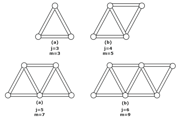
If the number of members in the truss is just sufficient to prevent distortion of its shape when loaded externally, it is called a perfect truss. A perfect truss satisfies the equation m = 2j-3, where j is the number of joints and m is the number of members.

Deficient or Collapsible or Imperfect Truss
When the number of members is less than 2j – 3, it is a deficient truss. It is an imperfect truss. It is also known as a collapsible truss, as under the action of collapsible forces, the truss tends to collapse.

Redundant Truss
An imperfect truss in which the number of members is more than 2j-3 is called the redundant truss.
2 force members– A member of the truss is a two-force member. Here, the forces are collinear; therefore, a truss member would be in tension or compression.
Types of Truss Based on Determinacy
If the number of unknown forces (reactions and internal forces) of a given structure is equal to equilibrium equations, the structure is known as a determinate structure. Determinacy is of two types; one is Internal Indeterminacy other is External Indeterminacy.
- Statically Determinate Truss
- Statically Indeterminate Truss
Statically Determinate Truss
If it is possible to determine the reactions, forces, and internal forces in members of a truss by applying an equilibrium equation, that truss is known as a Statically Determinate Truss. To design or analyze a truss, it is essential to determine the force in each member. The main purpose is to check whether the members can carry the applied loads without failing.A truss is considered statically determinate if all of its support reactions and member forces can be found using only the equilibrium equations. For a planar truss to be statically determinate, the number of members added to the number of support reactions must not exceed the number of joints multiplied by 2. This condition is the same as that used previously as a stability criterion.
Assumptions:
While solving problems on Statically Determinate Trusses, we consider some assumptions like, Members are subjected to axial forces only (Compression or Tension), Shear Force and Bending Moment are neglected, Self Weight of the members is ignored, Members are assumed to be linear, All joints are smooth, frictionless hinges, Loads and Reactions will act directly or indirectly at joints only.
Degree of Static Indeterminacy
- DS = m+re – 2j
where, DS = Degree of static indeterminacy m = Number of members, re = Total external reactions, j = Total number of joints - DS = 0 ⇒ Truss is determinate
If Dse = + 1 Dsi = –1 then DS = 0 at specified point. - DS > 0 ⇒ Truss is indeterminate.
Statically Indeterminate Truss
If it is impossible to determine the truss members’ reaction forces and internal forces by applying equilibrium equations, it is known as a Statically Indeterminate Structure. It is defined as structures that can’t be statically analyzed using only equilibrium equations (statics). These structures indicate that there’s at least one more unknown force than there are equations of equilibrium, meaning that the sum of forces and moments in each direction is equal to zero.
In 2D structures, there are three equations of equilibrium. Statically Indeterminate Structures are analyzed by Force method or Displacement method. In the Force method, redundant forces are treated as unknowns. In the Displacement method, displacements are treated as unknown.
Zero Force Members
Some members don’t carry any load. They are known as Zero Force Members. There are different ways to find these zero-force members. The purpose of Zero Force Members is to provide stability to the structure and to avoid failure because of unexpected loads. Some of the ways are:
- In a pin joint, if the number of members is three and two of the members are in the same line, the force in the third member is zero. ( No load, No reaction at the joint )
- At the pin joint, if the number of members is 2 and they are in different lines, then the force on both members is zero. ( No load, No reaction shall be present at that joint)
Truss Member Carrying Zero forces
(i) M1, M2, M3 meet at a joint
M1M2 are collinear
⇒ M3 carries zero force
where M1, M2, M3
represents member.
(ii) M1 M2 are non collinear and Fext = 0
⇒ M1 M2 carry zero force.
Assumptions in Truss Analysis
Analysis of a Truss is generally a complex process. We need to simplify such a process. It is physically impossible for all these conditions to be satisfied exactly in an actual truss. Therefore, an ideal truss in which these idealized conditions are assumed is called an ideal one.
We make some assumptions in the truss analysis that significantly simplify the process. Some assumptions are as follows:
- Members are inter-connected only at their ends.
- Members are connected at joints by frictionless pin.
- Loads must only be applied at joints.
- Self-weight of the member may be neglected.
- Members must be straight.
- A pin connection can represent all the joints in the structure, i.e., those members are free to rotate at the joints.
- The members of a truss are rigidly connected using a gusset plate.
- Loads are only applied at the joints of the truss. Loads are never applied in the middle of the member as all joints are pinned, and members cannot carry Bending Moment; they can carry only Axial Loads.
- Each member has to be in equilibrium. Therefore, the forces acting at each end of the member must be equal and opposite.
Sign Convention and Graphical Representation of Internal Forces
In the analysis of trusses, we will use the positive sign for tensile force and the negative sign for compressive force. In addition to this, the graphical representation of the direction of internal forces is described as follows –
- If the direction of force is away from the joint, then it means that the force in the member is tensile.
- If the direction of force is towards the joint, then it means that the force in the member is compressive.
Method of Truss Analysis
Truss analysis can be done via various methods. While designing trusses, it is essential to know the forces acting on each element of the truss to design it according to the safety factor. The two commonly used methods for truss analysis are:
- Method of joint
- Method of section
Methods of Joints
Method of Joints is used to find the unknown forces acting on members of a truss. Method of Joints is usually the fastest and most convenient way to discover the unknown forces in truss structure. The equilibrium of a joint is considered in the Method of Joints. Following are the steps that need to be followed to use this method.
- Draw a Free Body Diagram of the truss and solve for reaction forces. Use equilibrium equations to calculate the reaction force.
- Draw FBD of each joint and solve the internal forces. (Unknown forces are found using equilibrium equations.) The force will act away from the joint for members in tension, and for members in compression, the force will act towards the joint.
FBD
Example:
Taking equilibrium of the horizontal forces.
∑Fx = 0, HA= 0
Equilibrium of Vertical Forces
∑Fy = 0
FA+ FE= 20kN
MC= 0
dFA= dFE
FA= 10kN
FE= 10 kN
To find force in each joint.
E.g. – Joint A
FAB = -10/Sin 60 = –11.5kN
FAC = FAB Cos 60 = – 5.75 kN
Like this, we can find out forces in each joint.
Disadvantages of Method of Joints
To find out the forces in any internal member, we must find the forces in prior members. Hence, the Method of Joints is a lengthy method. Hence, it is a time taking method. Another disadvantage of this method is that if the number of members is greater than two, then this method is not suitable.
Method of Section
The equilibrium of a structure is considered in the Method of Sections. In this method, we need to pass a section through the member which we have chosen. A section may divide the entire structure into two separate parts. It is preferred that the section must pass through three members. It is a time-effective method as there is no need to find the force in a prior member to find the force in any chosen internal member. A section may be horizontal, inclined, or vertical. Following are the steps that need to be followed to use this method.
- Draw a Free Body Diagram of the truss and solve for reaction forces. Use equilibrium equations to calculate the reaction force.
- Cut the truss through the members of interest.
- Apply the equilibrium equations to solve the internal forces.
If you are preparing for GATE and ESE, avail Online Classroom Program to get unlimited access to all the live structured courses and mock tests from the following link:


