
- Home/
- GATE ELECTRONICS/
- GATE EC/
- Article
Microwave Engineering : Introduction to Microwave Engineering and EM Wave Propagation
By BYJU'S Exam Prep
Updated on: September 25th, 2023

Laws of Electricity & Magnetism
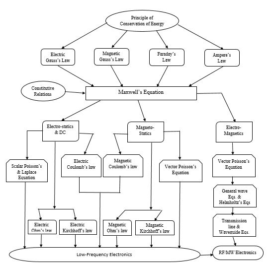
These are the following laws of Electricity and Magnetism:
- Electric flux & enclosed charge
- Magnetic flux & enclosed charge
- EMF induced ∝ time varying magnetic flux
- DC current flow generates H.flux
- D=εE; B=μH; J=σE
- Behavior of EM fields/wave
- Static Electric field (char. capacitor)
- Static Magnetic field (magnet/DC ‘I’)
- E.field->M.field->E.field->.
- Potential function in charged region & free-space
- Force between charged particles
- Force between Magnetic Poles
- Magnetic Potential function due to current distribution.
- Time varying fields/waves
- Linear resistor law
- Voltage and current law
- Linear reluctance law
- Magnetic flux & MMF laws
- Time harmonic fields/waves
Maxwell's Equation
- For Static fields (δ/δt=0) Maxwell’s equations are:
- D = ρ
- ∇•B = 0
- ∇ × E = 0
- ∇ × H = J
- where, D = ε E and B = μ H (ρ, J are the charge, current Densities)
- For Time varying fields Maxwell’s equations are:
- ∇•D = ρ
- ∇•B = 0
- ∇×E = -δB/δt
- ∇ × H = J + δD/δt
- Faraday's Law (∇ × E = – δB/δt) shows that time-varying magnetic field (δB/δt) is a source of the electric field (E).
- Ampere’s Law (∇ × H = J + δD/δt) shows that both electric current (J) or time-varying E-field (δD/δt) are sources for the magnetic field (H).
- Thus, in the source-free region (ρ = 0 and J = 0), time-varying electric and magnetic fields can generate each other.
- Consequently, EM fields are self-sustaining, thus predicting the phenomenon of EM wave propagation.
Electromagnetic (EM) Signal spectrum
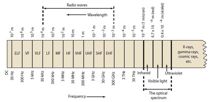
- Signal wavelength, λ=λ0/√(εrμr);
- λ0=c/f ; velocity, v = c /√(εrμr) and
- β = ω/v
RF/MW versus DC/Low – AC signals: MW Engineering
- In LF, mostly l<<λ, thus I & V are constant in line. (l = device length)
- In HF, mostly l >> λ, thus I & V are not constant in the line.
- Unwanted HF effects of component insulating-shell & wire-lead
- Current distribution within the conductor [Skin Depth, δs = √(2/ωμσ) and Surface resistance, Rs = 1/(δsσ) = √(ωμ/2σ)]
A few reasons for using RF/Microwaves
- Wider bandwidth due to higher frequency
- Smaller component size leading to smaller systems
- More available frequency spectrum with low interference.
- Better resolution for radars due to smaller wavelengths
- High antenna gain possible in a smaller space
Some Disadvantages in using RF/Microwaves
- More expensive components
- Existence of higher signal losses
- Use of high-speed semiconductor devices
RF/Microwave Applications
- Medical: Imaging, selective heating, sterilization etc.
- Domestic/industrial: Cooking, traffic & toll management, sensor
- Surveillance: Electronic warfare, security system etc.
- Radar: Air defense, guided weapon, collision avoidance, weather
- Astronomy & Space exploration: Monitor and collect data.
- Communication: Satellite, Space, Long distance telephone, etc
Introduction to RF/Microwave Communication
- In 1960’s: Microwave was 1stused for wireless communication between Europe and America. It required repeater stations for approximately every 30 to 50 miles .
- In 1970~1980’s: Fiber-optic link was introduced and repeaters were used for approximately every 2000 miles.
- In 1990’s: Microwave Satellite links were introduced. The High-orbit and Low-orbit satellites were used since then.
Guided Transmission Media
- Coaxial TL : Low radiation, freq. range up to3GHz, support TEM mode
- Two-wire TL: Low radiation, freq. up to300 MHz, support TEM mode
- Waveguide: For high freq./power signals, Support TE/TMmodes.
- Microstrip: Losy, quasi-TEM modes, high bandwidth, easy integration
- Stripline: Less losy, TEM, high bandwidth, low power capacity, Fair’’


TEM: Electric & Magnetic field comparatively are perpendicular to each other and also to the direction of proportional.
More on guided Transmission Media
- Suspended-substrate stripline, easy for device integration.
- Slot line: very useful for specific applications.
- Coplanar line: Conductor and GND is in the same plane


Free space propagation (Plane Waves)
- Plane wavefronts (circular, spherical or rectangular plane)
- Uniform Plane wave; E & H fields are uniform in plane-wave-front.
- Plane Wave conditions; δE/δx = δE/δy = δH/δx = δH/δy= 0 (as prop in z-dir)
- The solution of Maxwell's equations for a uniform plane wave in source-free-region results in the expressions of E & H field intensities as: Ex = Eo e(jωt-γz) = Eo cos(ωt-βz) OR Hy = Ho e(jωt-γz) = Ho cos(ωt-βz) ; where Eo & Ho are E & H field magnitudes; γ= α+jβ= jω√εμ{as α=0}
- Plane waves in air/vacuum (εr = μr = 1); the phase constant βo=ω√εoμo; the intrinsic wave impedance ηo = Eo/Ho = √μo/εo = 377Ω{λo = 2π/βo = c/f}
Basic characteristics of the uniform plane wave in a source free region
- There is no E or H field component along the direction of proportional (z).
- Two pairs of the E & H fields {(Ex, Hy) OR (Hx, Ey)} produces two independent plane waves, which can exist and propagate by itself.
- E and H field components are always ⊥to each other; (Ex, Hy) or (Hx, Ey)
- Ratio of E and H field components are constant (intrinsic wave imp)
- If reflection of the wave occurs due to some obstacles in the propagating path.
- Standing wave is generated from the incident and reflected waves.
Polarization of waves
- Polarization of wave depends on magnitude and phase relationship between existing E-field components (Ex and Ey)
- Linear polarization occurs when Ex and/or Ey are in phase regardless of their relative magnitudes (direction of L.P. wave is the same as E-field)
- E-field of a L.P. EM wave: E(z,t) = [A ax + B ay] cos(ωt -βz-φ)
- Circular polarization occurs when Ex & Ey are out of phase by 90° but both components have equal magnitude.
- E-fields of an L.P. EM wave are: Ex = A cos(ωt + fy + π/2 + βz) and Ey = A cos(ωt + fy + βz)
- Elliptical polarization occurs when Ex and Ey are out of phase by 90° and both components have different magnitudes.
- E-fields of E.P. wave: Ex = A cos(ωt+ fy + π/2 + βz) and Ey = B cos(ωt + fy + βz)
- Example: use a probe to measure E & H fields of L. polarized EM wave
EM wave propagation and attenuation
- Use two horn antennas, one connected with the source (mW power and 9GHz) and the other one is connected with a speaker (load). By moving the receiving Horns, we can show the power radiation pattern of the load (attenuation and main-lobe)
- Reflection of EM wave: Microwave reflects from metal plates with a reflected wave angle equal to the incident wave angle. This is due to the acceleration of the free electrons in the metal (caused by the incident EM wave), which in-turn produce an EM wave traveling away from the metal plate (called reflected EM wave). Since in a semiconductor material, a number of free electrons are less, less amount of reflection occurs and more incident EM wave is absorbed.
- Interference in EM wave propagation: The constructive and destructive interference in the receiver is shown (~height of the receiver)
- Guided EM wave propagation: In the rectangular waveguide: correct guide size is important for guiding EM waves properly.
Microwave Integrated Circuits (MICs)

Microwave Frequency bands Designation frequency range
- L-band 1 to 2 GHz
- S-band 2 to 4 GHz
- C-band 4 to 8 GHz
- X-band 8 to 12 GHz
- Ku-band 12 to 18 GHz
- K-band 18 to 26.5 GHz
- Ka-band 26.5 to 40 GHz
- Q-band 30 to 50 GHz
- U band 40 to 60 GHz
- V-band 50 to 75 GHz
- E-band 60 to 90 GHz
- W-band 75 to 110 GHz
- F-band 90 to 140 GHz and D band 110 to 170 GHz
Thanks.
Team Gradeup.


