
- Home/
- GATE ELECTRONICS/
- GATE EC/
- Article
Time Domain & Frequency Analysis Notes for GATE EC 2022 Exam
By BYJU'S Exam Prep
Updated on: September 25th, 2023

In this article, you will find the Notes on Time Domain and Frequency Analysis of Linear Circuits which will cover the topic as Introduction to Time domain and Frequency Domain, Transient Responses and Transient Analysis of Different Circuits, Parallel and Series Resonance.
Table of content
Time Domain
- Resistance (R)
- Capacitance (C) and
- Inductance (L)
The behaviour of a circuit composed of R, C, and L elements and it is modelled by differential equations with constant coefficients.
- An electrical system is said to be in a steady state when the variables describing its behaviour (voltages, currents, etc.) are either invariant with time (d.c. circuits) or are periodic functions of time (a.c. circuits).
- The time-varying currents and voltages resulting from the sudden application of sources, usually due to switching, are called transients.
- An electrical system is said to be in transient state when the variables are changed non-periodically, i.e., when the system is not in steady-state.
- The transient response is the fluctuation in current and voltage in a circuit (after the application of a step voltage or current) before it settles down to its steady state.
In a DC circuit, the electro‐motive forces push the electrons along the circuit and resistors to remove that energy by conversion to heat. In AC circuits, currents vary in time, so we have to consider variations in the energy stored in electric and magnetic fields of capacitors and inductors, respectively.
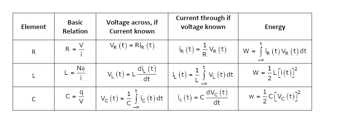
Note: VR, VL and VC are the voltages across R, L and C respectively while iR, iL and iC are the current through R, L and C respectively.
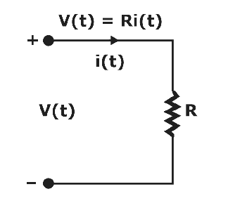
- Time Domain:
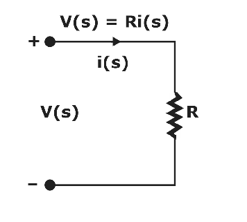
- s-Domain:
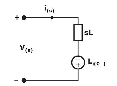
Inductor:
- Time Domain:
![]()

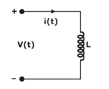
- s-Domain:
V(s) = L[sI(s) – i(0)]

Capacitor (C):
- Time Domain:


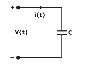
- s-Domain:
i(s) = sCV(s) – Cv
![]()

Steps for Finding Transient Response
- Identify the variable of interest (Inductor current for RL circuit, Capacitor voltage for RC circuit).
- Determine the initial value of the variable.
- Calculate the final value of the variable.
- Calculate the time constant for the circuit.
Transient Response of RL and RC Circuits


Transient Analysis of R-L Circuit:

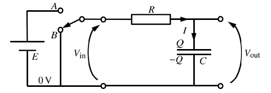
- When the switch is closed, current flows into the capacitor.
- Current flow ceases when the charge collected on the capacitor produces a voltage equal to and opposite to V.
- An equation describing the behaviour is shown; it is both exponential and asymptotic.
- The value RC is called the time constant (τ) in the equation.
- As τ grows smaller, transient behaviour disappears much faster.
The transient current through the inductor L at any time t

- When the switch is closed, current flow is inhibited as the inductor develops an opposite voltage to the one applied.
- Current slowly begins to flow as the inductor voltage falls toward 0.
- As the transient effect dies, the current flow approaches V/R.
- The time constant τ in an RL circuit is defined as τ = L/R.
- As τ grows smaller, transient behaviour disappears much faster.
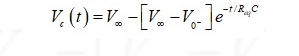
The transient voltage across capacitor C at any time t:

- A circuit with R, L, and C can exhibit oscillatory behaviour if the components are chosen properly.
- For many values of R-L-C, there will be no oscillation.
- α is the damping factor that determines the rate at which the oscillation dies out.
- The smaller L and C, the higher frequency of the oscillation.
- If R is too large, the quantity under the square root is negative, which means there is no oscillation.
Frequency Domain
- A periodic signal can be viewed as being composed of a number of sinusoids.
- Instead of specifying a periodic signal in terms of the time variable t, one can equivalently specify the amplitude and phase density of each sinusoid of frequency contained in the signal.
- It uses the frequency variable ω as an independent variable, and thus it is said to be the frequency domain of the given time domain signal.
KCL in s-domain:

- t-domain (time domain): i1(t)+i2(t)-i3(t)+i4(t)=0
- s-domain (complex frequency domain): I1(s)+I2(s)-I3(s)+I4(s)=0
KVL in s-domain: 
- t-domain (time domain): -v1(t)+v2(t)+v3(t) = 0
- s-domain (complex frequency domain): -V1(s)+ V2(s)+V3(s) =0
Signal Sources in s Domain: Voltage Source:
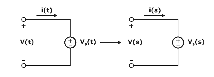
- t-domain: v(t) = vs(t), and i(t) depends on circuit.
- s-domain: V(s) = Vs(s), and I(s) depends on circuit.
Current Source:
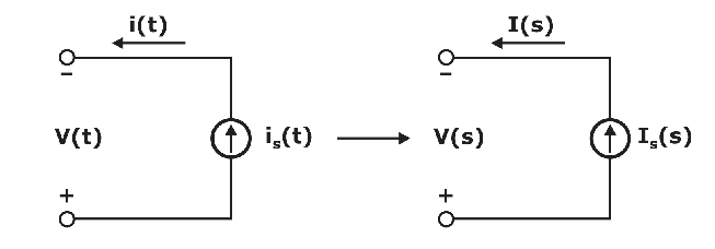
- t-domain: i(t) = is(t), and v(t) depends on circuit.
- s-domain: I(s) = Is(s), and V(s) depends on circuit.
For more information about the time domain analysis and second order system, you can refer to the following video available on the Byju Exam Prep’s official youtube channel.
Resonance: The circuit is said to be in resonance if the current is in phase with the applied voltage. The power factor of the circuit at resonance is unity. At resonance, the circuit behaves like a resistive circuit. The frequency at which the resonance occurs is called the resonant frequency.
There are two types of Resonance circuits: 1. Series Resonance circuit and 2. Parallel Resonance circuit.
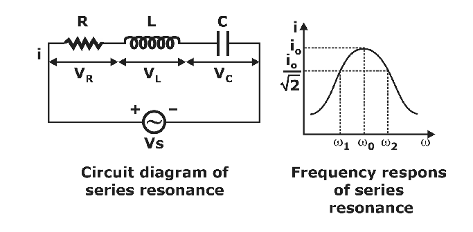
Series Resonance
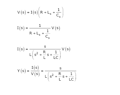
The series RLC can be analyzed in the frequency domain using complex impedance relations.
If the voltage source above produces a complex exponential waveform with complex amplitude V(s) and angular frequency s = σ + iω , KVL can be applied:
At resonance
|VL| = |VC| and these are 180° out of phase.
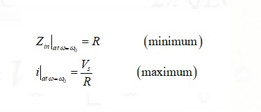
Zin = Input impedance
The frequency at which the inductance and capacitance react cancel each other is this circuit’s resonant frequency (or the unity power factor frequency).
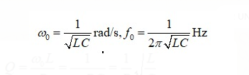
Conditions for ω and ω0 in Series Resonance

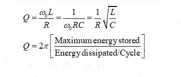
Quality factor: Quality factor or Q-factor is basically an amplification factor for a resonant circuit.
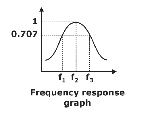
Bandwidth: The bandwidth (ω2 – ω1) is called the half-power bandwidth or 3-dB bandwidth.
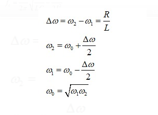
The bandwidth of the series circuit is defined as the range of frequencies in which the amplitude of the current is equal to or greater than(1/1.414) times its maximum amplitude. This yields the bandwidth B = ω2 – ω1 = R/L.
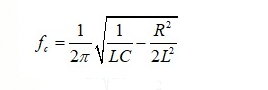
The frequency at which voltage across the inductor is maximum
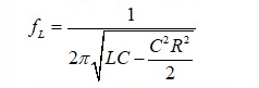
The frequency at which voltage across the capacitor is maximum
Selectivity It is defined as the ratio of resonant frequency to the bandwidth.

Key Points
- Selectivity of series R-L-C circuit with C variable is
 .
. - Selectivity of series R-L-C circuit with L variable is also
- The higher the’ selectivity, the higher will be the quality factor.
- The higher the selectivity, the lesser will be the bandwidth.
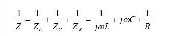
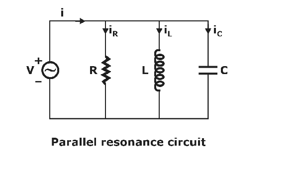
Parallel Resonance
A parallel resonance circuit is also called an anti-resonance circuit. The complex admittance of this circuit is given by adding up the admittances of the components:
At resonance,
- |iL| = |iC| and these are 180° out of phase
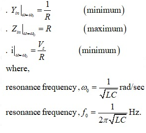
Conditions for ω and ω0 in Series Resonance

A parallel RLC circuit is an example of a band-stop circuit response that can be used as a filter to block frequencies at the resonance frequency but allow others to pass.
If you aiming to crack GATE & ESE, Other PSU Exams then you must try Online Classroom Program to get unlimited access to all the live structured courses and unlimited mock tests from the following links:
ESE and GATE EC Online Classroom Program (24+ LIVE Courses and 150+ Mock Tests)
ESE and GATE EE Online Classroom Program (24+ LIVE Courses and 193+ Mock Tests)
Click on the Links Below to Avail Test Series:
Click Here Avail GATE/ESE EC Test Series !!! (150+ Mock Tests)
Click Here Avail GATE/ESE EE Test Series !!! (193+ Mock Tests)
 Daily free APP and Youtube classes, Engineering Jobs, Free PDF & much more, Join our Telegram Group Join Now.
Thanks
#DreamStriveSucceed


