
- Home/
- GATE ELECTRONICS/
- GATE EC/
- Article
Vibration & Shock Study notes For Instrumentation Engineering
By BYJU'S Exam Prep
Updated on: September 25th, 2023

In this topic we will deal with the concept Vibration & Shock also along with we cover the topic such as Displacement (linear and angular), Velocity, Acceleration, Force & Torque Measurement.
Displacement Measurement
Measurement and control often involve monitoring rotary and linear motion. Measurement and control are multi-stage processes with the first stage of either process, the generation of an electrical signal, to represent the motion. When measurement is the objective, this signal is used to quantify the desired property (i.e., displacement, velocity, etc.), and the data are translated to a format that can be understood by the end user. When control is the objective, the signal is used directly by the associated controller.
Major types of transducers used to monitor motion are
Proximity Switches:
- Proximity switches, probably the oldest of the control elements, are basically location sensing devices. They include true mechanical switches, photo sensors, magnetic pickups, pressure sensors, etc.
- Proximity switches have historically been the primary location indicating device in control systems, but rarely used for measurement except in “go-no-go” gauging.
- discrete change in signal level give the output.
POTENTIOMETER’S (Rotary & Linear) :
- Potentiometer output from rotary and linear devices, depend on the position of a sliding contact on a resistive element.
- It normally operated as a voltage divider, output is analog, and analog to digital hardware is required for digital output.
- Potentiometers are often used to measure displacement as opposed to proximity switches whose chief function is control safety or limiting.
- Potentiometers are moderately accurate devices when properly calibrated, but are susceptible to degradation due to wear.
- Resolution may be limited, but is often adequate for many applications. Potentiometers are susceptible to many environmental constraints. Essentially mechanical contact devices, they must be protected from shock, vibration, and foreign matter contamination.
Analog Inductive Components:
- Inductive type of transducers generally used for rotary and linear applications.Position can be deduced accurately with external electronics and output is sinusoidal.
- There are many variations of inductive transducers. Some of the most common are synchros, resolvers, induction potentiometers, and linear variable differential transformers (LVDTs).
Encoders
- Encoders can be categorized into two broad types: contacting and non-contacting.
- The contacting type requires brushes or finger sensors that electrically transmit a signal to indicate a change in position.
- Non contacting encoders rely on magnetic, capacitive or optical phenomena to sense the motion.
- Rotary position sensing, either absolute or incremental, indicate the rotation of a shaft. The encoding disc is patterned with radial lines that are sensed as the input shaft is rotated. Mechanical packaging varies greatly depending on application requirements.
- Linear position sensing depends upon a moving head whose motion is sensed along a linear track and a scale.
Measurement of Velocity
- Velocity is a vector that consists of a magnitude (speed) and a direction.
- A linear velocity transducer (LVT) is an inductive device that is similar in principle to the linear variable displacement transducer (LVDT)
discussed previously. - Doppler radar velocity measurement: Namely, a noise (such as a car horn) moving towards you (or away from you) has an apparently higher (or lower) pitch or frequency, since the wavelength of the sound that reaches your ears is compressed (or stretched) due to the relative motion.
- Lagrangian velocity measurement: Lagrangian velocity measurements consist of following or tracking a fluid particle that is “marked” or identified in some way (dye in liquids, smoke in air, tiny soap bubbles in air, tiny particles in water – it is assumed that
the tiny particles move with the fluid; this is called seeding the flow). Some call this time-of-flight velocity measurement. - Particle image velocimetry: A high-tech velocity measurement device for fluid flows is called particle image velocimetry (PIV).
- Eulerian velocity measurements: Eulerian velocity measurements involve a probe or sensor of some kind sitting in a fluid flow.In this technique instead of tracking individual marked fluid particles, we measure the velocity of the fluid that happens to be flowing past the sensor at the time of measurement.
- Practical measuring instruments for velocity:
(i) Pocket size thermal anemometer
(ii) Pocket size vane anemometer
(iii) Compact Vane Anemometer
(iv) Large-Area Vane Anemometer
(v) Compact Thermal Anemometer
(vi) All-rounder for ventilation and indoor air quality
(vii) Pitot tube reference instrument
(viii) Reference service instrument for Pitot tube measurement
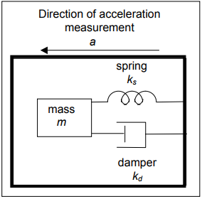
Measurement of Acceleration
- The measurement of acceleration starts by modelling the basic structure at the heart of any accelerometer: a moving mass connected to a damper and spring.
- Seismic Accelerometer: response of the basic so-called Seismic accelerometer, which consists of mass that is connected to the frame by a spring and damper.
.
- Closed loop version of the Seismic Accelerometer: This has the advantage of improving the dynamic response, increasing accuracy and reducing nonlinearities.
- Types of Accelerometer: Any accelerometer can be classified based on the following:
1. Type of spring element.
2. Method of damping.
3. Method of displacement detection.
- Resistive Type: This type is suitable for slowly varying accelerations and low frequency vibrations in the range of 0 to 50 g.Resolution of 1 to 400; a cross sensitivity of ±1%; inaccuracy of around ±1%; a life expectancy of around 2 million reversals. It has a typical weight of 500 gm and a typical size of 125cm3.
- Strain gauge/Piezoresistive Type: The sensor used within these types of devices serves as a spring element and a mass. They have a typical range of around 200 g; a resolution of around 1:1000; an inaccuracy of ±1%; cross sensitivity of ±2%. They are generally of smaller size and weight than the resistive types weighing around 25 gm at a size of around 3 cm3.
- LVDT Type: The LVDT in general has the advantage over resistive potentiometric device that it does not offer any resistance to movement and that there is no contact. LVDT devices have a range of 700 g.
- Variable inductance/variable capacitance Type: These devices have a range of around 40 g. They suffer an inaccuracy of ±0.25% of full scale, have a resolution of 1:10 000, and a cross sensitivity of 0.5%.
- Piezoelectric Type:The piezoelectric crystal acts as spring and damper. These devices are smaller in size around 15 cm3 and a weight of around 50 gm. They are not suitable for slowly varying or constant accelerations, resolution of ±0.1%, an inaccuracy of ±1% and offer a large of measurement in one device (0.03 g to 1000 g). They are also produced in intelligent versions.
- Micro-sensors: With the advent of MEMS and NEMS, accelerometers can now be micro machined. They usually consist of a small mass mounted on a thin Silicon membrane. Displacement is measured by the use of a piezoresistor deposited on the membrane or a capacitor etched on it.
Measurement of Force
Force/Stress measurement is important in many engineering applications such as
- Weighing of an object
- Dynamics of vehicles
- Control applications such as deployment of air bag in a vehicle
- Study of behavior of materials under different types of loads
- Vibration studies
- Seismology or monitoring of earthquakes
There are many methods of measurement of a force. Some of these are given below:
- Force may be measured by mechanical balancing using simple elements such as the lever.
- Simplest method is to use a transducer that transforms force to displacement.
- Force measurement by converting it to hydraulic pressure in a piston cylinder device.
- Force measurement using a piezoelectric transducer.
Force to displacement conversion: A spring balance is an example where a force may be converted to a displacement based on the spring constant.
F= KX
where k is spring constant; x displacement; F applied force
Conversion of force to hydraulic pressure: While discussing pressure measurement we have discussed a dead weight tester that essentially consisted of a piton cylinder arrangement in which the pressure was converted to hydraulic pressure. It is immediately apparent that this arrangement may be used for measuring a force.
Piezoelectric force transducer: A piezoelectric material develops an electrical output when it is compressed by the application of a force.This signal is proportional to the force acting on the material. We shall discuss more fully this later.
Measurement of torque
Torque and power are important quantities involved in power transmission in rotating machines like engines, turbines, compressors, motors and so on.Torque and power measurements are made by the use of a dynamo-meter.
Torque Measurement
- Brake Arrangement
- Load electrically – Engine drives a generator
- Measure shear stress on the shaft
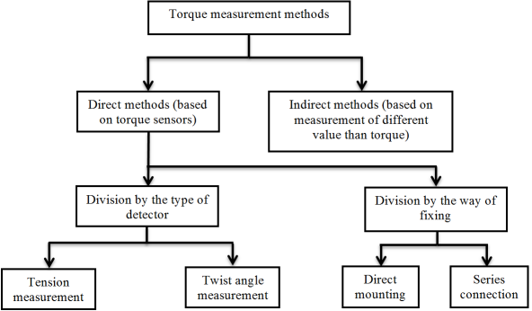
Torque Measuring Sensors:
- Rotary Torque Transducers
- Slip Ring/Shaft Torque Transducers
- Slip Ring/Square Drive Torque Transducers
- Slip Ring/Special Apps Torque Transducers
- Rotary, Non-Contact Torque Transducers
- Wireless Telemetry (Rotary Measurement)
- Wireless Telemetry (Clamp-on Measurement)
- Flanged Reaction Torque Transducers
- Special Reaction Configs Torque Transducer
- Miniature Reaction Torque Transducers
- Shaft Reaction Torque Transducers
- Square Reaction Drive Torque Transducers
- Torque/Thrust Reaction Torque Transducers
- Torque Watch Reaction Torque Transducers
Vibration & Shock Measurement
- Vibration is an oscillation wherein the quantity is a parameter defining the motion of a mechanical system.
- Oscillation is the variation, usually with time, of the magnitude of a quantity with respect to a specified reference when the magnitude is alternately greater and smaller than the reference.
Useful Application of Vibration: Vibration is generated intentionally in component feeders, concrete compactors, ultrasonic cleaning baths and pile drivers, for example. Vibration testing machines impart vibration to objects in order to test their resistance and function in vibratory environments.
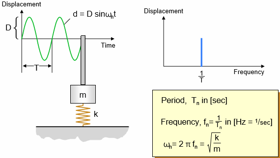
figure of simple form of vibrating system
Why do we measure Vibration
- To verify that frequencies and amplitudes do not exceed the material limits.
- To avoid excitation of resonances in certain parts of a machine
- To be able to dampen or isolate vibration sources
- To make conditional maintenance on machines
- To construct or verify computer models of structures
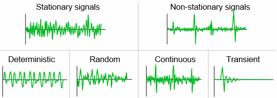
Vibrating Signals: In order to make the analysis, we must first talk about the types of vibration signals we might encounter and how we measure these signals.
Types of signals:
List of Vibration Measuring Instrument
- Impulse & Continuous Vibration Measurrment
- Measuring Vibration with Accelerometer
- Measuring Vibration with Displacement sensor
- Measuring Vibration with Probe Mounting
- Instantaneous Vibration & Total Vibration
- High Temperature Piezoelectric Vibration Sensors
- Hand-held And Other Mounting Methods For Industrial Sensors
SHOCK: Mechanical shock is a short burst of vibratory energy. If the shock is infinitely short it will also have a frequency spectrum which is distributed continuously with frequency. Since a shock will always have a finite length its frequency spectrum will be limited to a band of frequencies.
Shock measurement is of interest in several fields such as
- Propagation of heel shock through a runner’s body.
- Measure the magnitude of a shock need to cause damage to an item: ‘’’fragility’’’.
- Measure shock attenuation through athletic flooring.
- Measuring the effectiveness of a Shock Absorber.
- Measuring the shock absorbing ability of package cushioning.
- Measure the ability of an athletic helmet to protect people.
- Measure the effectiveness of shock mounts.
- Determining the ability of structures to resist seismic shock: earthquakes, etc.
- Determining whether personal protective fabric attenuates or amplifies shocks.
- Verifying that a Naval ship and its equipment can survive explosive shocks.
Shocks Measuring Instrument
- Accelarometer
- Laboratory Instrumentation
- Stand-alone shock Data Logger
All the Best.
Team Gradeup!


