
- Home/
- GATE ELECTRONICS/
- GATE EC/
- Article
Single Stage Amplifier
By BYJU'S Exam Prep
Updated on: September 25th, 2023

A Single Stage Amplifier can amplify effectively if the transistor is biased correctly. So, to improve the strength of the weak signal, single-stage amplifiers play a vital role. In the applications like communication and medical and scientific investigations for showing the results in the indicating instruments, we will use a single-stage amplifier.
In Multistage amplifiers, we will connect multiple single-stage amplifiers in a cascade. So, to understand the operation of multistage amplifiers, one should know the operation of a single-stage amplifier. So, in this article, we will focus on the operation of Single stage amplifier and its essential parameters.
Download Formulas for GATE Electronics & Communication Engineering – Control System
Table of content
What is a Single Stage Amplifier?
An electronic circuit is said to be a single-stage amplifier if it consists of a single transistor with proper bias and additional components based on the requirement that will provide an output, which is then an amplified version of any input quantity like the voltage, current, and power. That means Transistor is the main component in single-stage Amplifiers.
Among all the transistors, BJT is the basic one. Hence, it is easy to understand single-stage amplifiers using JFET or MOSFET after studying and understanding the working of amplifiers using BJT in a single stage. We can analyze the multistage amplifiers by analyzing every single circuit stage.
Download Formulas for GATE Electronics & Communication Engineering – Digital Circuits
Simple Circuit Diagram of Single Stage Amplifier
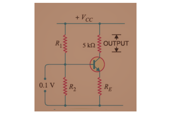
The simple circuit diagram of a single-stage amplifier is shown below.
Practical Circuit Diagram of Single Stage Amplifier
In the simple circuit diagram of a single-stage amplifier, we have considered one Bipolar Junction Transistor (BJT) and four resistors. The resistors R1 and R2 are used to provide a bias to the Transistor in the circuit. The resistors RC and RE are connected to BJT’s collector and emitter terminals, respectively.
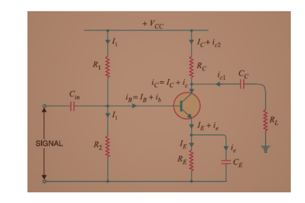
Basically, in this circuit diagram, the BJT and one resistor are connected to each terminal of the BJT. For practical purposes, we will connect one capacitor to each terminal of the BJT to pass the AC and block DC at the input and output terminals of the BJT.
The practical circuit diagram of a single-stage amplifier is shown below. Here, we considered the load resistor, RL.
Download Formulas for GATE Electronics & Communication Engineering – Electronic Devices
Equivalent Circuits of Single-Stage Amplifier
We will provide the DC supply to the single-stage amplifier circuit for biasing the Transistor. To get the amplified signal at the output, we will apply the AC signal at the input terminals of the Transistor. For easy analysis of the circuit, we will use the superposition theorem. Since we have two types of signals accordingly, we will get the following two equivalent circuits.
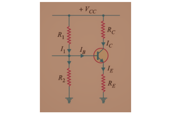
- DC Equivalent Circuit: We will get the DC equivalent circuit of a single-stage amplifier by open circuit the capacitors and making the AC voltage value zero by short-circuiting the AC voltage terminals. This DC equivalent circuit is shown below. Since only the DC supply is present in the circuit, we can calculate the DC voltages and DC currents in the circuit.
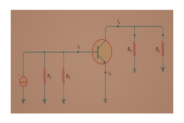
- AC Equivalent Circuit: We will get the AC equivalent circuit of a single-stage amplifier by short-circuiting the capacitors and making the DC voltage value zero by short-circuiting the DC voltage terminals. This AC equivalent circuit is shown below. Since only AC supply is present in the circuit, we can calculate the AC voltages and AC currents.
If you are preparing for GATE and ESE, avail Online Classroom Program to get unlimited access to all the live structured courses and mock tests from the following link:


