Control Volume Analysis
By BYJU'S Exam Prep
Updated on: September 25th, 2023

Control volume analysis is the analysis of the control volume considered in the analysis of the pipe flow. A control volume is a volume in space considered for analyzing a particular term. In fluid mechanics, the control volume is considered to analyze the different losses in the pipe flow. The control volume analysis is required before the analysis of the pipe flow.
Control Volume Analysis PDF
Control volume analysis is the process of analyzing a control volume, which is established with the help of mathematical tools. With respect to the internal frame of reference, the control volume is assumed to be fixed, or it can be considered to be moving at the same speed as the fluid. This article contains basic notes on the “Control Volume Analysis” topic of the “Fluid Mechanics & Hydraulics” subject.
Table of content
What is Control Volume Analysis?
Control Mass
- A fixed mass of a fluid element in the flow field is identified, and conservation equations for properties such as momentum, energy, or concentration are written.
- The identified mass moves around in the flow field.
- Its property corresponds to the same contents of the identified fluid element that may change from one location to another.
Control Volume
- This approach is popular and widely applied in the analysis.
- An arbitrarily fixed volume located at a certain place in the flow field is identified, and the conservation equations are written.
- The property under consideration or analysis may change with time.
Momentum Equation in Control Volume Analysis
It is based on the law of conservation of momentum or on the momentum principle, which states that the net force acting on a fluid mass is equal to the change in momentum of flow per unit of time in that direction.
F.dt = d(mv) ………… (1)
which is known as the impulse-momentum equation and states that the impulse of a force F acting on a fluid of mass m in a short interval of time dt is equal to the change of momentum d(mv) in the direction of the force.
Force exerted by a flowing fluid on a pipe bend.
The impulse-momentum equation (1) determines the resultant force exerted by a flowing fluid on a pipe bend.
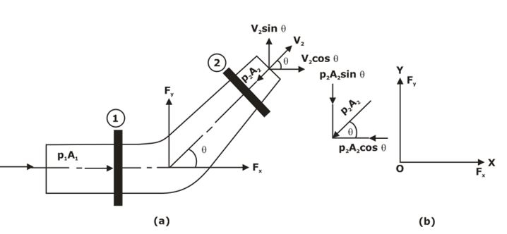
Let v1, p1 and A1 are the velocity, pressure and area at section 1 of the pipe.
and v2, p2, A2 = corresponding values of velocity, pressure and area in section (2).
Let Fx = horizontal component of the force exerted by the fluid element on the bend in the x-direction.
Fy = vertical component of the force exerted by fluid element on the bend in the y-direction
The momentum equation in the x-direction is given by,
P1A1 – P2A2 cosθ – Fx = ρQ (V2Cosθ- V1) ……………… (2)
Similarly, the momentum equation in the y-direction gives
P2A2 sinθ – Fy = ρQ (V2 sinθ – 0) ………………. (3)
Fy = ρQ (- V2 sinθ) – P2A2sinθ
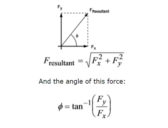
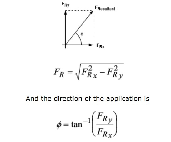
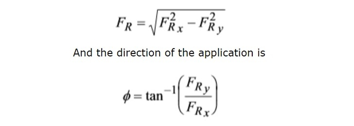
Now the resultant force (FR) acting on the bend,
FR= (F2x + F2y)0.5
And the angle made by the resultant force with horizontal direction is given by
tanθ = Fy/Fx
Moment of Momentum Equation
The moment of momentum equation is derived from the moment of momentum principle, which states that the resulting torque acting on a rotating fluid equals the rate of change of the moment of momentum.
According to the moment of momentum principle,
Resultant torque = rate of change of moment of momentum
T = ρQ [V2r2 – V1r1]
The momentum equation relates the sum of the forces to the acceleration or rate of change of momentum

From the conservation of mass,
mass into face 1 = mass out of face 2
The rate at which momentum enters face 1 is
ρ1A1u1u1 = mu1
The rate at which momentum leaves face 2 is
ρ2A2u2u2 = mu2
Thus the rate at which momentum changes across the stream tube is
ρ2A2u2u2 – ρ1A1u1u1 = mu2 – mu1
The Momentum equation is:
F = m(u2 – u1)
F = Qρ(u2 – u1)
This force acts on the fluid in the direction of the flow of the fluid
- If the Motion is not one-dimensional.

We consider the forces by resolving in the directions of the coordinate axes.
The force in the x-direction
Fx = m(u2 cosθ2 – u1 cosθ1)
= m(u2x – u1x)
or
Fx = Qρ(u2 cosθ2 – u1 cosθ1)
= Qρ(u2x – u1x)
And the force in the y-direction
Fy = m=u2 sinθ2 – u1 sinθ1)
= m(u2y – u1y)
or
Fy = Qρ(u2 sinθ2 – u1 sinθ1)
= Qρ(u2y – u1y)
The resultant force can be found by combining these components.
Application of Momentum Equation
The momentum equation has various applications in fluid mechanics problems. With the help of the momentum equation, a very complex problem can be solved easily. Here momentum equations are explained for the condition of a pipe flow in different conditions.
Force due to the flow around a pipe bend
A converging pipe bend lying in the horizontal plane turning through an angle of Θ.

- As the fluid changes direction, a force will act on the bend.
- This force can be very large in the case of water supply pipes. The bend must be held in place to prevent breakage at the joints.
Taking Control Volume
In the x-direction
FTx = ρQ(u2x – u1x)
u1x = u1
u2x = u2 cosθ
FTx = ρQ(u2 cosθ – u1)
In the y-direction
FTy = ρQ(u2y – u1y)
u1y = u1sin 0 = 0
u2y = u2 sinθ
FTy = ρQ(u2 sinθ – u1)
It can also be written by using Bernoulli Equations

where hf is the friction loss (this can often be ignored, hf=0)
As the pipe is in the horizontal plane, z1=z2 And with continuity, Q= u1A1 = u2A2

Knowing the pressures at each end, the pressure force can be calculated,
FP = Pressure force at 1 – Pressure force at 2
FPx = ρ1A1 cos 0 – ρ2A2 cosθ = ρ1A1 – ρ2A2 cosθ
FPy = ρ1A1 sin 0 – ρ2A2 sinθ = – ρ2A2 sinθ
There are no body forces in the x or y directions, so FRx = FRy = 0
The body force due to gravity is acting in the z-direction, so it need not be considered
FRx = FTx – FPx – 0
= ρQ(u2 cosθ – u1) – ρ1A1 + ρ2A2 cosθ
FRy = FTy – FPy – 0
= ρQu2 sinθ + ρ2A2 sinθ
The resultant force on the fluid is given by
Impact of a Jet on a Plane
To determine the impact force of a jet on a plane, we also require the control volume analysis of the flow. The impact force on a jet can be calculated by equating the total energy of the flow before and after the striking of the flow with the help. It is explained below with detailed information.
A jet hitting a flat plate (a plane) at an angle of 90º
The reaction force of the plate. i.e., the force the plate will have to apply to stay in the same position

In the x-direction
FTx = ρQ(u2x – u1x)
FTx = -ρQu1x
The system is symmetrical, so the forces in the y-direction cancel, so Fy = 0
The pressures at the inlet and the outlets to the control volume are atmospheric. So, the pressure force is zero.
Fpx= Fpy= 0
As the control volume is small, we can ignore the body force due to gravity, FBx= FBy= 0
FTx = FRx + FPx + FBx
FRx = FTx – 0 – 0
FRx = -ρQu1x
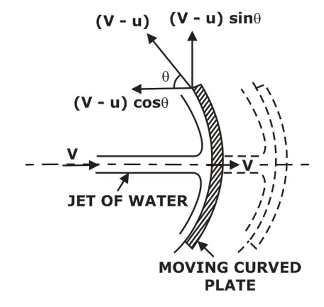
Force on a Curved Vane
Force on a curved vane can be calculated with the control volume analysis of the flow. With the help of momentum equations in both directions, it can be calculated easily. The force calculation on a curved vane is explained below in detail.
- Pressures at ends are equal, which is equal to atmospheric pressure.
- The cross-section and velocities (in the flow direction) remain constant.

Total force in the x-direction
FTx = ρQ(u2 – cosθ)
by continuity equation, u1 = u2 = Q/A
FTx = -ρQ2(1 – cosθ)/A
In the y-direction
FTy = ρQ(u2 sinθ- 0)
FTy = ρQ2/A
- The pressure at the inlet and the outlets to the control volume are atmospheric, Fpx=Fpy=0.
- Nobody forces in the x-direction, FBx=0
- In the y-direction, the body force acting is the weight of the fluid.
- If V is the volume of the fluid on the vane, then FBX= ρgV.
The resultant force in all directions are
FTx = FRx + FPx +FBx
FRx = FTx = -ρQ2(1 – cosθ)/A
FTy = FRy + FPy +FBy
FTy = FRy = ρQ2/A
And the resultant force on the fluid is given by
The force on the vane is the same magnitude but in the opposite direction, R= -FR.
Force Exerted by the Jet on a Stationary Vertical Plate
Consider a jet of Water coming out from the nozzle strikes a flat vertical plate,
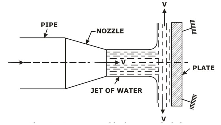
Fx = ρaV[V – 0]
Fx = ρaV2
Force exerted by the jet on a curved plate(vane) when the plate/vane is moving in the direction of the jet,
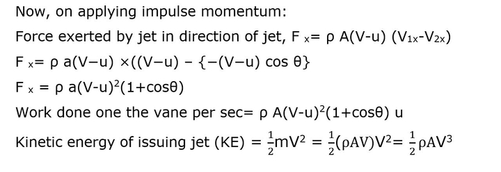
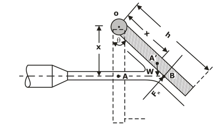
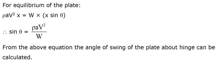
Force Exerted by a Jet on a Hinged Plate
Consider a jet of water striking a vertical plate at the center which is hinged at O. Due to the force exerted by the jet on the plate, the plate will swing through some angle about the hinge, as shown in Fig.