
Slope Deflection Method Study Notes for Civil Engineering
By BYJU'S Exam Prep
Updated on: September 25th, 2023

The slope deflection method is one of the methods of determining the deflection of the structural member like a beam, column, etc. Various methods are available to determine a structure’s slope and deflection, including the slope deflection method.
Slope Deflection Method PDF
The slope deflection method for finding the deflection of the structures is a displacement method of analysis of indeterminate structures. Read here the fundamental notes on the “Slope Deflection Method” topic of the “Structural Analysis” subject.
Table of content
-
1.
What is the Slope Deflection Method?

-
2.
Assumptions in the Slope Deflection Method
-
3.
What is the Degree of Freedom?
-
4.
Sign Conventions for Slope Deflection Method
-
5.
Fixed End Moments for Different Beam Support
-
6.
Slope Deflection Equation
-
7.
Application of Slope-Deflection Method to Statically Indeterminate Beams
-
8.
GATE Weightage Analysis of Structural Analysis
What is the Slope Deflection Method?
The slope deflection method is a method of analysis of indeterminate structures. This is a stiffness method to find out the deflection.
- The stiffness method takes displacements (rather than forces) as unknown quantities. For this reason, the method is also called the displacement method.
- The unknown displacements are obtained by solving equations of equilibrium (rather than equations of compatibility) that contain coefficients in the form of stiffnesses.
In this method, if the slopes at the ends and the relative displacement of the ends are known, the end moment can be found in terms of slopes, deflection, stiffness and length of the members.
In the slope-deflection method of structural analysis, the rotations of the joints are treated as unknowns. For any one member bounded by two joints, the end moments can be expressed in rotations. In this method, all joints are considered rigid; i.e. the angle between members at the joints is considered not to change in value as loads are applied. The slope defection method is applicable for beams and frames. It is useful for analysing highly statically indeterminate structures with low kinematical indeterminacy.
Assumptions in the Slope Deflection Method
The slope deflection method for analysis of indeterminate structures uses displacements and rotations as the unknown parameters. This method is based on the following simplified assumptions.
- All the joints of the frame are rigid, i.e, the angle between the members at the joints does not change when the members of the frame are loaded.
- Due to axial and shear stresses being very small, distortion is neglected.
What is the Degree of Freedom?
The number of joints rotation and independent joint translations in a structure is called the degrees of freedom. The degree of freedom can be expressed in two types. And, it can be explained as follows:
- In Rotation- For beam or frame is equal to Dr.
Dr = j – f
Where,
- Dr = degree of freedom.
- j = no. of joints, including supports.
- F = no. of fixed support.
In translation- For frame is equal to the number of independent joint translations which can be given in a frame. Each joint has two joint translations, the total number of possible joint translations = 2j. Since, on the other hand, each fixed or hinged support prevents two of these translations, and each roller or connecting member prevents one of these translations, the total number of the available translational restraints is
2f + 2h + r + m
Where,
- f = number of fixed supports
- h = number of hinged supports
- r = number of roller supports
- m = number of supports
The degree of freedom in translation can be expressed as
Df = 2j – (2f + 2h + r + m)
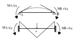
Sign Conventions for Slope Deflection Method
Sings conventions should be fixed before analysing indeterminate structures, whether carried out with the slope deflection method or any other method. Only deflections and slope and the ends are considered unknowns, while analysis is carried out by the slope deflection method.
- Joint rotation and fixed moments are considered positive when occurring in the clockwise direction.
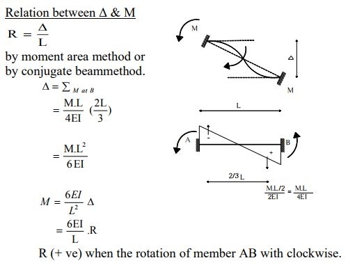
Relation Between End Moments and Rotations:
MA = (4EI/L)θA
MB = (2EI/L)θA
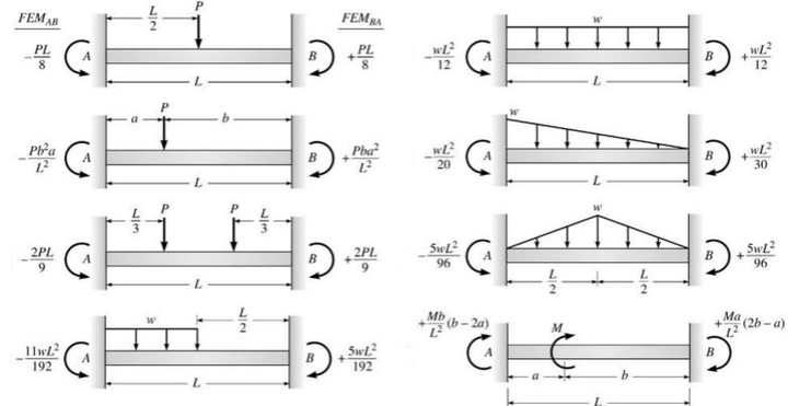
Fixed End Moments for Different Beam Support
In the slope deflection method of analysis of indeterminate structures, only slope and deflections are the unknown parameters of the analysis. But these parameters can correlate with the fixed end moments at the supports. So, the idea about the fixed end moment is necessary to carry out further steps with these methods.
Slope Deflection Equation
The slope Deflection equation relates to the slope and deflection of the structural members at different ends. In this method, joints are considered rigid. It means joints rotate as a whole, and the angles between the tangents to the elastic curve meeting at that joint do not change due to rotation. The basic unknown is joint displacement (θ and Δ).
To find θ and Δ, joint equilibrium conditions and shear equations are established. The forces (moments) are found using force-displacement relations. Which are called slope deflection equations.
Slope Deflection Equation:
(i) The slope deflection equation at the end A for member AB can be written as:

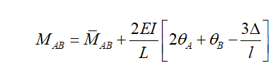
(ii) The slope deflection equation at the end B for member BA can be written as:

where,
- L or l = Length of the beam, EI = Flexural Rigidity
- M‾AB = M‾BA are fixed end moments at A & B, respectively.
- MAB & MBA are the final moments at A & B, respectively.
- θA and θB are rotations of joints A & B, respectively.
Δ = Settlement of support
- Sign Convention
- +M → Clockwise
- -M → Anti-clockwise
- +θ → Clockwise
- -θ → Anti-clockwise
- Δ → +ve, if it produces clockwise rotation to the member & vice-versa.
The number of joint equilibrium conditions will be equal to the number of ‘θ’ components & number of shear equations will be equal to the number of ‘Δ’ Components.
Application of Slope-Deflection Method to Statically Indeterminate Beams
The procedure is the same whether it is applied to beams or frames. It may be summarized as follows:
1. Identify all kinematic degrees of freedom for the given problem. This can be done by drawing the deflection shape of the structure. All degrees of freedom are treated as unknowns in the slope-deflection method.
2. Determine the fixed end moments at each end of the span to the applied load. The table given at the end of this lesson may be used for this purpose.
3. Express all internal end moments in terms of fixed end moments and near-end and far-end joint rotations by slope-deflection equations.
4. Write down one equilibrium equation for each unknown joint rotation. For example, at support in a continuous beam, the sum of all moments corresponding to an unknown joint rotation at that support must be zero. Write down as many equilibrium equations as there are unknown joint rotations.
5. Solve the above set of equilibrium equations for joint rotations.
6. Now, substituting these joint rotations in the slope-deflection equations evaluates the end moments.
7. Determine all rotations.
For more information about the slope deflection method, you can refer to the following video on Byju Exam Prep’s official youtube channel.
GATE Weightage Analysis of Structural Analysis
Here we are providing the GATE CE previous year weightage analysis to understand the importance of the subject in the GATE Exam.
| Year | Set 1 | Set 2 |
| GATE 2021 | 6 | 6 |
| GATE 2020 | 5 | 6 |
| GATE 2019 | 4 | 5 |
| GATE 2018 | 2 | 4 |
| GATE 2017 | 3 | 4 |
Check out some important notes listed below:
If you are preparing for ESE/ GATE or other PSU Exams (Civil Engineering), then avail Online Classroom Program for ESE and GATE CE:
Online Classroom Program for ESE/GATE CE
You can avail of BYJU’S Exam Prep Test Series, specially designed for all Civil Engineering Exams:


