
Torsion of Shafts
By BYJU'S Exam Prep
Updated on: September 25th, 2023

When a torque or twisting moment is applied on a shaft, shear stress is developed in the shaft. Torsion of shafts is twisting of the shaft about its longitudinal axis. Torsion of shafts is a type of deformation in shafts. The moment which leads to a twisting moment is known as Torque.
In this article, we will try to see the Torsion of shafts, Torsional Shear Stress, Strength of these shafts, their design, and the power transmitted by these shafts. Torsion and Torque have many practical uses in real life. Let us discuss torsion of shafts.
Table of content
What is Torsion of Shafts?
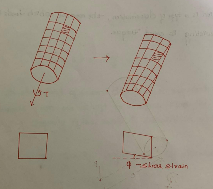
To get a better understanding of the Torsion of Shafts, let us suppose, a force ‘P’ which is acting at a distance ‘e’ from the centre generates a moment T, which acts along the longitudinal axis. The applied torque causes the bar to deform by twisting. In the case of an axis-symmetric section, the body will rotate relative to each other when the torque is applied but the body will not deform. A bar that is not axis-symmetric when subjected to torsion results in warping of bar cross-section.
Torsional Shear Stress
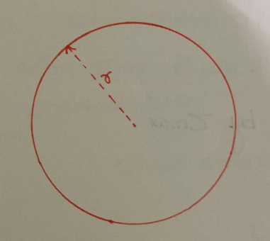
It is the shear stress offered by a body to twisting moment or torque. In Torsion of Shafts, it is the shear stress resisted by the shafts when they are subjected to twisting moment or torque. Suppose a shaft of radius ‘r’ is subjected to a Torsional Moment ‘T’.
Torsional Shear Stress will be given by:
τ/r= T/J
Where,
- τ = Shear Stress
- r = Radial Distance from Centre of Shaft
- T = Torsional Moment
- J = Polar Moment of Inertia
Problems on the torsion of shafts can be solved using the above formula.
τ= Tr/J
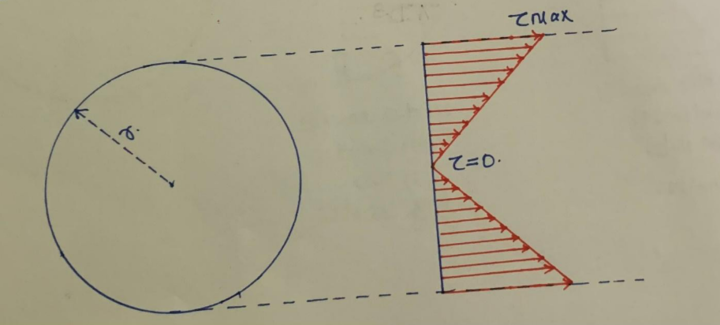
Shear Stress in a Shaft due to torsion moment is having a linear distribution.
Shear Stress due to torsion on the shaft is maximum at extreme fiber where r=D/2.
Shear Stress due to torsion on the shaft is zero at the centre.
Maximum Shear Stress is given by τmax
τmax= Trmax/J
where rmax=D/2
τmax= T/ZP
Where
- ZP = Polar Section Modulus
- ZP= J/rmax
- ZP= πD3/16
- τmax= 16T/πD3
Problems with torsion of shafts can be solved using the above formula.
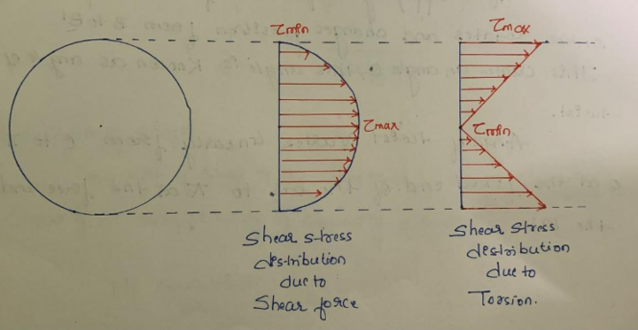
Shear Stress is developed due to shear force (V) as well as torsion or Torque (T). Shear stress distribution due to shear force is parabolic with zero shear stress at extreme fiber and maximum shear stress at centre. Shear Stress due to shear force is given by
τ= Vay/Ib
Shear Stress Distribution due to torsion is linear with maximum shear stress at extreme fiber and zero at the centre.
τ= Tr/J
τmax for a hollow circular section is given by
τmax= T/ZP
ZP= D3(1-K4)/16
Where, k = d/D
d = Inner Diameter
D = Outer Diameter
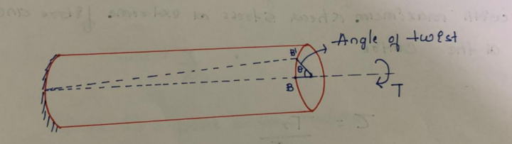
After applying torque, the free end of the section rotates and changes position from B to B’. This creates an angle θ, which is known as angle of twist. The angle of twist varies linearly from 0 to π at the free end of the bar.
Θ= TL/GJ
Where,
- L = Length of the bar
- T = Torsion/Torque applied
- G = Shear Modulus
- J = Polar Moment of Inertia
- GJ – Torsional Rigidity
Strength of Shafts
The strength of shafts is the torsional moment carrying capacity or torque carrying capacity of a shaft. We know that,
τmax= T/ZP
T= τmax/ZP
T- Torsional moment carrying capacity / Torsional strength
τmax≲ τP
Where τp is the permissible shear stress.
Strength of Solid Shaft
Ts= πds3τp/16
ds – Diameter of Solid Shaft
Torsion of Shafts
d ≥ (16T/πZP)1/3
(For Solid Shafts)
d ≥ (16T/π(1-k4)ZP)1/3
(For Hollow Shafts)
d ≥ 32TL/πGΘP
Where ΘP is the permissible angle of twist.
Power Transmitted by Shaft
P=Tw=2πNT/60
w=2πf
f= N/60
Where,
- f = Rotations per Second
- N = Rotations per minute
Problems on Torsion of Shafts
1. Find the maximum shear stress in a shaft subjected to a torque of 2kN-m having a diameter of 50mm.
Solution-
Given, T = 2kN-m, D = 50mm
τmax= 16T/πD3
τmax= 16×2×106/π503=81.48 MPa
2. Find the angle of twist in a shaft subject to a torque of 40kN-m and having a diameter of 200mm and length 4m.
Solution-
Given, G = 80GPa = 80 x 103 MPa
T = 40 kN-m
D = 200mm
L = 4m
θ= TL/GJ = [40 × 106 ×4000] / [80 × 103 × π/32 × 2004]=0.0127 radians or 0.73º
3. A circular shaft of 60mm diameter is requested to transmit torque from one shaft to another. Find the torque carrying capacity of the shaft if permissible shear stress is 40MPa.
Solution-
Given, ds = 60mm, τp = 40MPa
Ts = τpZp
= τp x π/16 x d3
= 40 x π/16 x 603
= 1.69 kN/m
4. Find the power transmitted by a circular shaft of diameter 100mm, number of rotations 150rpm, and maximum shear stress 60MPa.
Solution-
Given, D = 100mm, N = 150rpm
τmax= 16T/πD3
60= 16 × T ×1000/ π×1003
T = 11780.97 N-m
P=2πNT/60= 2 ×150 ×11780.97/60000
P = 185 KW
5. Find the diameter of a shaft having a number of revolutions of 150 rpm. Maximum Shearing Stress is 80 N/mm2 and Power transmitted by the shaft is 400KW.
Solution-
P=2πNT/60
400=2π ×150 ×T/60000
T = 25464.8 N-m
τmax= 16T/πD3
d= (16 ×25464.8 ×1000/π ×80)1/3=117.5mm
If you are preparing for GATE and ESE, avail Online Classroom Program to get unlimited access to all the live structured courses and mock tests from the following link:


