
What is OR Gate Truth Table?
By BYJU'S Exam Prep
Updated on: September 25th, 2023

OR Gate Truth Table: A logic gate is a physical device that performs a logical operation in one or more logical inputs and produces a single logical output. The output of a “Logic OR Gate” only returns “LOW” again when all the inputs are “LOW.” In other words, for the logic OR gate, any “HIGH” input will give a “HIGH” as output. OR gate truth table will help us understand this clearly.
Thus the logic OR gate truth table can be correctly described as an “Inclusive OR gate” truth table because the output is true when both gate inputs are true (HIGH). Therefore, we can define the operation of a 2-input logic OR gate as:
“If either A or B is true, then Q is true.”
Download Formulas for GATE Computer Science Engineering – Digital Logic
Table of content
What is an OR Gate?
The OR gate will have two or more inputs but only one output. A logical OR gate function effectively finds the maximum between two binary digits, such as the complementary AND function finds the minimum.
OR Gate Symbol
An OR gate can have two or more inputs, with at least one being true. The bits are set to one using the OR operator. The logical symbol for the OR gate is shown below:
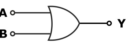
Thus, the logical boolean expression of the OR gate is Y = A+B.
Download Formulas for GATE Computer Science Engineering – Computer Organization & Architecture
What is the OR Gate Truth Table?
The OR gate truth table is a table that displays the output state based on the various combinations of input states. It demonstrates how an OR logic gate works. The truth table lists the output of a particular digital logic circuit for all the possible combinations of its inputs. For example, the truth table of a 2 input OR gate can be represented as: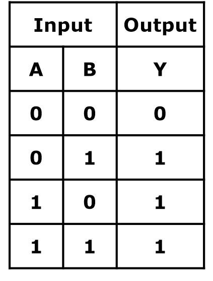
OR Gate Truth Table
It is clear from the truth table that if all the inputs or any of the inputs are high, the output Y is HIGH, whereas if all the inputs are LOW, then the output Y is low.
Download Formulas for GATE Computer Science Engineering – Operating Systems
Properties of OR Gate Truth Table
OR gate follows both commutative and associative laws:
- Commutative law: A + B = B+ A
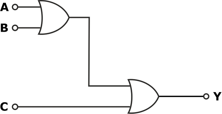
- Associative law: (A + B + C) = A + (B + C) = (A + B) +C
Enable and Disable Inputs for OR Gate
The representation of an OR gate is given below.
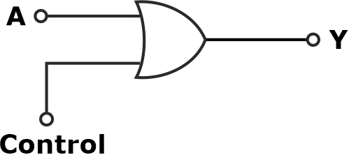
For control = 0; then the OR gate truth table will be:
|
A |
Control |
Y |
|
0 |
0 |
0 |
|
1 |
0 |
1 |
The change in the input causes the change in the output; hence, for OR gate logic, ‘0’ is an enable input.
For control = 1; the OR gate truth table will be:
|
A |
Control |
Y |
|
0 |
1 |
1 |
|
1 |
1 |
1 |
Due to change in the input, output remains the same; therefore for OR gate logic, ‘1’ is a disabled input.
The switching circuit diagram for the OR gate is shown:
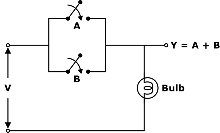
Here, the bulb will glow when any of the switches (either A or B) or both switches are closed.
In a multi-input OR gate, an unused input can be connected to
- Logic ‘0’ (Enable) or pull-down.
- Any of the user input.
- Left open or floating in case of ECL logic.
Out of these procedures, the best way is to connect to the logic ‘0’ or pull down.


