
JK Flip-Flop Excitation Table
By BYJU'S Exam Prep
Updated on: September 25th, 2023

Excitation Table of JK Flip-Flop: The Flip-Flop must be excited or triggered by the excitation table to move from its current state to the next one. It was created by using the truth table. In general, the truth table is used to illustrate how each Flip-Flop works. The truth table contains all the input combinations that cause the Flip-Flop to react and output the following state.
The excitation table of jk flip flop has one or two columns for each input and two columns for the current state (Qn) and the following state (Qn+1). The type of the Flip-Flop determines by the input columns. We will discuss the JK Flip-Flop excitation table in detail and its construction.
Download Formulas for GATE Computer Science Engineering – Digital Logic
Table of content
What is JK Flip-Flop?
The JK flip flop, a refined and enhanced form of the SR flip flop, was created to address the issue of the indeterminate state that occurs in the SR flip flop when both inputs are 1. In the JK flip flop, the input J acts as the input S of the SR flip flop, which was intended to set the flip flop, and the input K acts as the input R of the SR flip flop, which was intended to reset the flip flop.
The JK Flip-Flip is constructed with two methods that are as follows:
- By using SR Flip-Flop constructed from NOR latch
- By using SR Flip-Flop constructed from NAND latch
Download Formulas for GATE Computer Science Engineering – Computer Organization & Architecture
What is JK Flip-Flop Excitation Table?
This table’s leftmost column contains a list of all feasible FF output transitions in the JK Flip-Flop excitation table. For each transition, this column lists the FF’s CURRENT state, denoted by Qn, and the NEXT state, denoted by Qn+1. The J and K levels necessary for each transition are listed in the final column.
|
Output Transition |
Flip-Flop Inputs |
||
|
Qn |
Qn+1 |
J |
K |
|
0 |
0 |
0 |
X |
|
0 |
1 |
1 |
X |
|
1 |
0 |
X |
1 |
|
1 |
1 |
X |
0 |
Download Formulas for GATE Computer Science Engineering – Operating Systems
Construction of JK Flip-Flop Excitation Table
The JK Flip-Flop excitation table is derived from the JK flip-flop truth table information. The inputs are K = 0 or 1 and J = 0 from the truth table for the values of the current state and the next state, Qn = 0 and Qn+1 = 0 (marked in the first and third rows with yellow colour). K input is treated as a don’t care condition because it has two values (x).
As a result, when J = 0 and K = X, the state changes from Qn = 0 to Qn+1 = 0. The first row of the excitation table has it filled in.
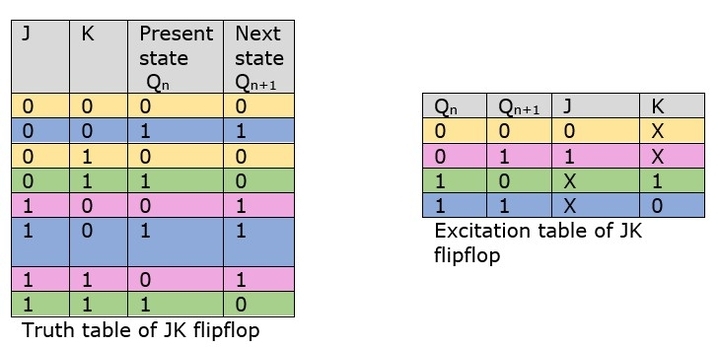
The inputs are J = 1, K = 1 or J = 1, K = 0, and the state transition from the current state Qn = 0 to the next state Qn+1 = 1 occurs (indicated in the fifth and seventh row with pink colour). As a result, the data Qn = 0, Qn+1 = 1, J = 1, and K = X are entered into the excitation table.
The inputs are J = 0, K = 1 or J = 1, K = 1 for the transition from state 1 to state 0. (indicated in the fourth and eighth row with green colour). Therefore, J = X and K = 1 are the necessary inputs for this transition because J can be either 0 or 1.
The J input can be 0 or 1, but the K input stays at 0 for the state transition from Qn = 1 to Qn+1 = 1. (indicated in the second and sixth row with blue colour). The excitation inputs required for this transition are J = X and K = 0.


