
Full Subtractor
By BYJU'S Exam Prep
Updated on: September 25th, 2023

The Full Subtractors are generally employed for ALU (Arithmetic Logic Unit) in computers to subtract as CPU & GPU for the applications of graphics to decrease the circuit difficulty. The full subtractor is the combinational circuit to perform subtraction using 3 bits.
Subtractors are mainly used for performing arithmetic functions like subtraction in digital devices and electronic calculators. Here, we will see what is a full subtractor in detail, along with its truth table and implementation.
Download Formulas for GATE Computer Science Engineering – Digital Logic
Table of content
What is a Full Subtractor?
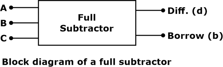
A full subtractor is an arithmetic circuit that performs a function of subtraction between two bits, considering that a lower significant stage may have borrowed a ‘1’. The Full Subtractor is one of the high-scoring concepts for the GATE exam. A full subtractor has three inputs and two outputs.
The full subtractor block diagram is shown below.
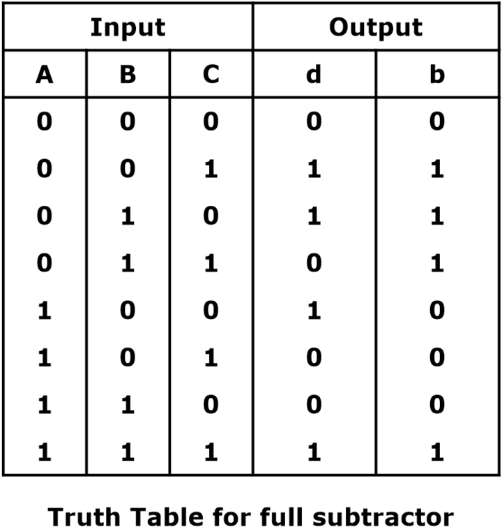
Full Subtractor Truth Table
The two inputs are A and B, and the third input is C. The output carry is designated as b(borrow), and the normal output is designated as d, which is the difference. This truth table is a highly important part of the GATE CSE syllabus. The truth table of a full subtractor is represented as given below:
Download Formulas for GATE Computer Science Engineering – Computer Organization & Architecture
Full Subtractor Equation
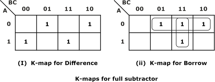
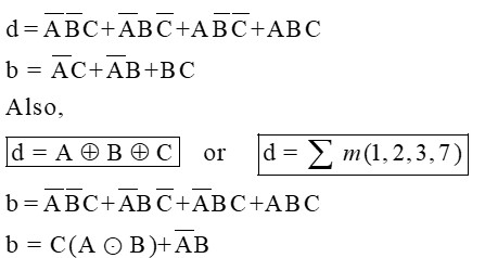
From the above truth table, the map for the outputs of the full subtractor is shown below, and the logical expression for the difference and borrow is as below:
Full Subtractor Expression
Download Formulas for GATE Computer Science Engineering – Operating Systems
Implementation of Full Subtractor Circuit
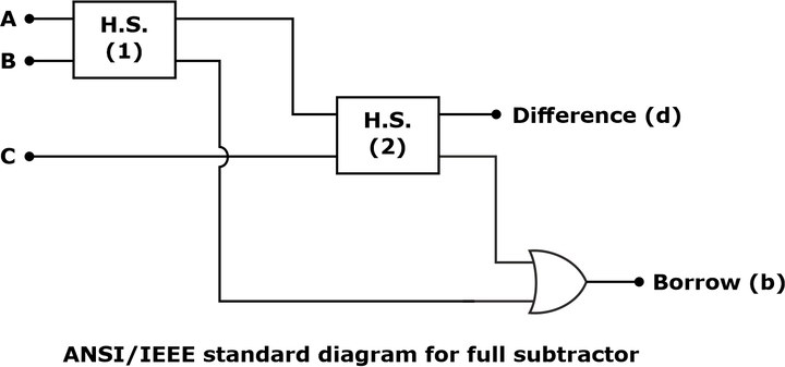
From the above expression, a full subtractor circuit can be realized in SOP form or with two half subtractors and an OR gate, as shown below:
Circuit Diagram of Full Subtractor
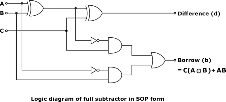
Full Subtractor Logic Diagram
The ANSI/IEEE standard logic diagram of the full subtractor is shown below:
The full subtractor can also be realized using a universal logic gate, either only NAND gates or NOR gates. The total number of NAND gates/Nor gates required to implement a full subtractor equals 9.


