
Combinational Circuits -1 Study Notes for GATE & Computer Science Engineering Exams
By BYJU'S Exam Prep
Updated on: September 25th, 2023

Combinational circuits form an essential part of digital logic design and are a crucial topic for students preparing for the Graduate Aptitude Test in Engineering (GATE) and other Computer Science Engineering exams. These circuits are designed to perform specific logical functions based on the current input values, without any memory element.
Here we are providing the complete study notes on the Combinational Circuits for the preparation of GATE, Computer Science Engineering Exam
Table of content
Logic Circuits
Logic Circuits can be divided into two types.
- Combinational Logic Circuit, and
- Sequential Logic Circuit.
Combinational Logic Circuit: A combinational logic circuit comprises digital logic gates whose output completely depends upon the combination of current inputs only.
- It consists of input variables, logic gate and output variables.
- No feedback is required.
- No memory is required.

- Examples of Combinational Circuits: Multiplexer, Decoder, Encoder, Parallel Adders, etc.
Sequential Logic Circuit: This Circuit consists of logic gates arranged in parallel and its output is determined by the combination of the current input and the prior output. Sequential circuit also contains memory elements that are capable to store the information of the prior output. 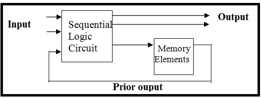
- Examples of Sequential Circuits: Flip-flops, Shift Registers, Counters, etc.
Logic Gates
Logic gate is an idealized physical device which is used to implement a Boolean function, logic gate is a miniature circuit that performs a logical operation on one or more logical inputs and produces a single logical output.
The logic gates can be classified as
- NOT, AND, OR, are basic gates.
- NAND, NOR are universal gates.
- EXOR, EXNOR are arithmetic circuit or code convertor or comparators.
GATE Computer Science Engineering Revision Sheet and Formulae
NOT Gate (Inverter)
Truth Table for NOT Gate:

Circuit Symbol for NOT Gate:

AND Gate


Properties of AND logic:
- Commutative Law: AB = BA
- Associative Law: ABC = (AB) C = (AC)B = A(BC)
OR Gate Truth Table


Properties of OR logic:
- Commutative Law: A + B = B + A
- Associative Law: (A + B + C) = (A + B) + C = A + (B+ C)
NAND Gate


Properties of NAND logic:
- Commutative Law:

- Associative Law:

NOR Gate


- NOR gate follows commutative law but not follow associative law
EXOR Gate
![]()


Properties of EXOR Logic:
- Enable input = 0
- Disable input = 1
- It is also called stair case switch.
- It is widely used in parity generation and detection.
- When both the inputs are different, then output becomes high or logic 1.
- When both the inputs are same, then output becomes low or logic 0.
Note:
![]()
EXNOR Gate


Properties of EXNOR Gate:
- Enable input = 1
- Disable input = 0
- When both the inputs are same, then output .becomes high or logic 1.
- When both the inputs are different, then output becomes low or logic 0.
Logic Gate Conversions
- OR Gate using NAND Gate:

- AND Gate using NOR Gate:

- NAND Gate using NOR Gate

- NOR Gate using AND Gate

NAND and NOR Gate as Universal Gate

NAND Gate as Universal Gate


![]()

![]()
Boolean Algebra
- NOT-Operation theorem:

- AND-Operation theorem:

- OR-Operation theorem:

- Distribution theorem: A + BC = A (A + B)(A + C)
Note: 
- Demorgan’s Theorem:


- Transposition Theorem: (A + B) (A + C) = A + BC
- Consensus Theorem: This theorem is used to eliminate redundant term. It is applicable only when if a boolean function contains three variables. Each variable used two times. Only one variable is complemented or uncomplemented. Then the related terms so that complemented or uncomplemented variable is the answer.


SOP (Sum of Product): (Minimum Term)
A sum of product expression is two or more AND functions or functions together. Each product term is known as minimum term.
- SOP expression is used when output becomes logic 1.
- Example:

- three minterms are there in the expression
POS (Product of Sum): (Maximum Term)
POS is defined as the AND function of two or more OR function in which each sum term is known as maximum term.
- POS expression is used when output is logic ‘0’.
- Example:

- Three max terms are there in the expression
Note:
With’ n’ variables maximum possible minimum and maximum terms = 2n
With’ n’ variables maximum possible logic expression = ![]()
Duality Theorem: To convert positive logic into negative logic and vice-versa, dual function are used.
- Change each AND sign by OR sign and vice versa (↔ +)
- Complement any 0 or l appearing in expression.
- Keep variable as it is.
- Example:

Representation of K-map: For n-variable Karnaugh-map, 2n cells are used to represent the boolean expression.
Example:
- 2 –variable K Map:

- 3 –variable K Map:

- 4 –variable K Map:

Remember, combinational circuits form a fundamental aspect of digital logic design, and a strong foundation in this area will be beneficial for various aspects of computer science engineering. By grasping the basics, practicing regularly, and solving a variety of problems, you can improve your understanding and excel in your exams. By studying the basics, mastering logic gates, understanding Boolean algebra, and practicing simplification techniques, you can enhance your problem-solving skills and approach these circuits with confidence. Best of luck with your exam preparation!
Thanks!!


