
- Home/
- GATE ELECTRICAL/
- GATE EE/
- Article
What is a Transmission Line? – Definition, Classification & Parameters
By BYJU'S Exam Prep
Updated on: September 25th, 2023

A transmission Line is used by electrical power systems to transfer electricity between any two distant points. In terms of electrical engineering, the Transmission Line is a set of conductors that is designed to transfer the power from the generating station to a far-end substation that is located near the load centers, in the most efficient and secure way.
The transmission line is generally made up of ACSR (aluminum conductor steel reinforced) type conductors, the steel is used to improve the mechanical strength of the conductor. The majority of strands in the ACSR conductor are made up of aluminum as it is a good conductor of electricity and its weight per unit length is less compared to copper. In this article, we will discuss the classification of transmission lines, transmission line parameters, and modeling.
Table of content
-
1.
What is a Transmission Line?

-
2.
Classification of Transmission Line
-
3.
Modelling of the Transmission Line
-
4.
Transmission Line Parameters or ABCD Parameters
-
5.
Assumptions in Transmission Line Modelling
-
6.
Modelling of Short Transmission Line
-
7.
Modelling of Medium Transmission Line
-
8.
Modelling of Long Transmission Line
What is a Transmission Line?
Transmission line are conductors that serve as a path for electrical waves to be transmitted through them. This essentially establishes a link between the transmitter and the receiver, allowing for signal transfer.
A transmission line allows electrical impulses to be transferred between two conducting wires separated by a dielectric medium, which is often air.
Classification of Transmission Line
In general, the transmission line will be classified on the basis of the length they have covered, but in practice, frequency is also a decisive parameter in the classification of the transmission line. Hence, the product of the length and frequency of a transmission line (lf) as the basis of the transmission line are classified into 3 types. They are namely:
- Short transmission line
- Medium transmission line
- Long transmission line
Short Transmission Line
If the product of length (l)and its operating frequency(f)of the transmission line is less than 4000, then the transmission line is known as a short transmission line. For the operating frequency of 50 Hz, the length of such a line will be less than 80 km.
Medium Transmission Line
If the product of length (l)and its operating frequency(f)of the transmission line is between 4000 to 10000, then the transmission line is known as a medium transmission line. For the operating frequency of 50 Hz, the length of the line lies between 80 km to 200 km. 4000≤lf≤10000
Long Transmission Line
If the product of length (l)and its operating frequency(f)of the transmission line is greater than 10000, then the transmission line is known as a long transmission line. For the operating frequency of 50 Hz, the length of the line will be greater than 200 km. lf>10000
Modelling of the Transmission Line
The physical ACSR conductor can be modeled in its electrical equivalent by using its parameters resistance, inductance, capacitance, and conductance. Here we will discuss how to model the transmission line by using the following parameters.
Resistance (R)
Every transmission line has certain values of resistivity (𝜌), length(l), and cross-sectional area (A), then the resistance of the transmission line is given by R=𝜌l/A
Inductance (L)
The current flowing through each phase of a transmission line will produce a magnetic flux between the conductors, the magnetic flux linkages per unit current through the conductor can be modeled as the inductance of the transmission line(L).
Capacitance (C)
The conductors of each phase are separated by air which is a dielectric material, hence whenever two current-carrying conductors are separated by a dielectric material there must be some capacitance (C) between the conductors. The effect of capacitance is significant in a medium and long transmission line and can be negligible in the analysis of a short transmission line.
Conductance (G)
The leakage current flowing through the insulators due to the insulator imperfections can be represented by the conductance (G) parameter. The effect of conductance is significant in a long transmission line, we neglect the effect of conductance in the analysis of short and medium transmission lines.
By using these four parameters the transmission line can be modeled as shown below
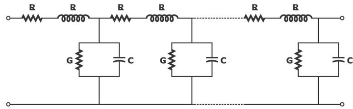
By using the R, L, G, and C the transmission line can be modeled as shown above but it is not possible to analyze the above circuit, hence with some basic assumptions and by using the ABCD or transmission line parameters we develop some basic models of the transmission line. Before that, we must have some basic knowledge of the ABCD or transmission line parameters.
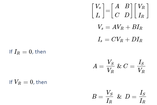
Transmission Line Parameters or ABCD Parameters
If Vs and IS are the voltage and current at the supplying end and VR and IR are the voltage and current at the receiving end of the transmission line, then the ABCD or transmission line parameters can be represented by the following equation.
Assumptions in Transmission Line Modelling
There are basic assumptions in the modeling of the transmission line they are:
- Assume that the system is balanced.
- Assume that the given network is lumped network, hence the R, L, C, and G can be represented for the tiny fractions of the network.
Modelling of Short Transmission Line
In the modeling of a short transmission line, the effect of capacitance and conductance are negligible. Hence by neglecting these we can draw the equivalent circuit as shown below.
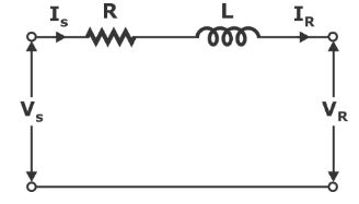
Z=R+jωL
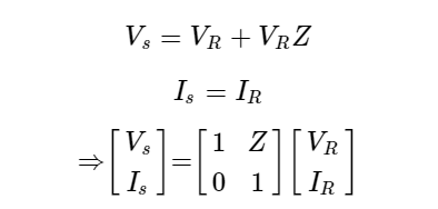
From the circuit
The above short transmission-line network can also be represented in the form of an admittance network as shown below.
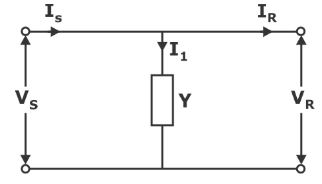
Vs=VR
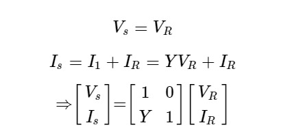
The calculations are similar in the admittance network and the portions that involve capacitors.
Modelling of Medium Transmission Line
In the analysis of the medium transmission line we consider the effects of R, L, and C only, we ignore the effect of the conductance in the analysis the of medium transmission line. The medium transmission can be modeled by using three methods they are namely:
- Nominal T-network
- Nominal 𝜋-network
- End condenser network
Nominal T-network
In the nominal T-network, the impedance of the transmission line is divided into two halves, and the capacitance of the entire transmission line is assumed to be concentrated in the middle of the transmission line as shown below.
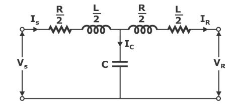
From here on I will directly give the ABCD parametric equation of each network by assuming that you can understand from the above discussion in the short transmission line, otherwise, you can follow them from our lectures.
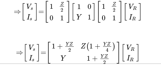
The analysis by using this method will induce some errors in the calculations as we assumed all the capacitance is concentrated in the middle of the transmission line, but this can be minimized by using the nominal 𝜋-network.
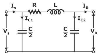
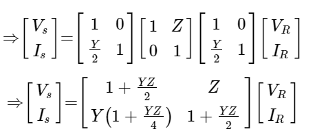
Nominal 𝝅-Network
In the nominal-𝜋 network, half of the capacitance is modelled at the supplying end, the remaining half at the receiving end as shown below.
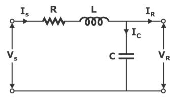
End Condenser Network
In the end condenser network entire capacitance of the transmission line is assumed to be concentrated at the receiving end of the transmission line as shown below.
Modelling of Long Transmission Line
In the modeling of a long transmission line, we must consider all four parameters such as R, L, C, and G. We use the rigorous method to model, maybe it’s not appropriate to discuss it here as it was a lengthy one, hence I’m providing the result here, we can discuss it elaborately in our lectures.
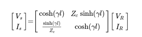
Where:
- γ=α+jβ=√(ZY) →propagation constant
- 𝛼→Attenuation constant
- 𝛽→Phase shift constantly
- l→Length of the transmission line
- Zc=√Z/Y →Characteristic impedance of the transmission line


