- Node:
- A point in a circuit where terminals of atleast two electric components meet. This point can be on any wire, it is infinitely small and dimensionless.
- Major Node:
- This point is a node. A set of these nodes is used to create constraint equations.
- Reference Node:
- The node to which Voltages of other nodes is read with regard to. This can be seen as ground (V = 0).
- Branch:
- This is a circuit element(s) that connect two nodes.
In electric circuits analysis, nodal analysis, node-voltage analysis, or the branch current method is a method of determining the voltage (potential difference) between "nodes" (points where elements or branches connect) in an electrical circuit in terms of the branch currents.
The node method or the node voltage method, is a very powerful approach for circuit analysis and it is based on the application of KCL, KVL and Ohm’s law.
The procedure for analyzing a circuit with the node method is based on the following steps.
Manual Nodal Analysis Algorithm:- Choose a reference node. (Rule of thumb: take the node with most branches connecting to it)
- Identify and number major nodes. (Usually 2 or 3 major Nodes)
- Apply KCL to identified major nodes and formulate circuit equations.
- Create matrix system from KCL equations obtained.
- Solve matrix for unknown node voltages by using Cramer's Rule (Cramer's Rule is simpler, although you can still use the Gaussian method)
- Use solved node voltages to solve for the desired circuit entity.
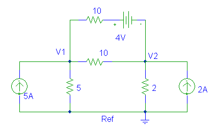
Example 1: Solve for the current through the 5 ohm resistor and the current through the 4V source using Node-Voltage Analysis.
Solution:
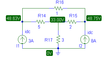
First, select a reference node and label the other nodes. Since each node has the same number of connected branches (4), we'll simply choose the bottom node as the reference. There are only two other nodes, which we will label V1 and V2.
Now write KCL at each node (except the reference):Solution: First, select a reference node and label the other nodes. All the nodes have three connected branches, so we will simply choose the bottom node as the reference.
6 V1 - V2 - 5 V3 = 15
-6 V1 + 31 V2 - 15 V3 =0
-2 V1 -V2 +3 V3 = 16
Finally, solve the 3 equations in 3 unknowns.V1 = 48.625V
V2 = 33 V
V3 = 48.75V
The current through the 5 ohm resistor can be found by Ohm's law:I = (V1 - V2)/5 = 3.125A
The voltage over the 3A source is simply V1, or 48.625V.
Mesh Analysis:
- Mesh analysis is another general procedure for analyzing circuits, using mesh currents as the circuit variables.
- Using mesh currents instead of element currents as circuit variables reduces the number of equations that must be solved simultaneously.
- Nodal analysis applies KCL to find unknown voltages in a given circuit, while mesh analysis applies KVL to find unknown currents.
- Mesh analysis is not quite as general as nodal analysis because it is only applicable to a circuit that is planar.
- A planar circuit is one that can be drawn in a plane with no branches crossing one another; otherwise it is nonplanar.
- A circuit may have crossing branches and still be planar if it can be redrawn such that it has no crossing branches.
- The mesh method uses the mesh currents as the circuit variables.
- Branch:
- This is a circuit element(s) that connect two nodes.
- Loop:
- This is a closed path in a circuit. A set of these loops are used to create constraint equations.
- Mesh:
- A loop passing through at least one branch. A mesh is defined as a loop which does not contain any other loops.
The mesh method uses the mesh currents as the circuit variables. The procedure for obtaining the solution is similar to that followed in the Node method.
Manual Mesh/Loop Analysis Algorithm:- Choose a conventional current flow.
- Identify and Number loops or meshes. (Usually 2 or 3 meshes/loops)
- Apply KVL to identified meshes/loops and formulate circuit equations.
- Create Matrix system from KVL equations obtained.
- Solve Matrix for unknown Mesh Currents by using Cramer's rule (it is simpler although you can still use Gaussian method as well)
- Used solved Mesh Currents to solve for the desired circuit entity.
 Solution: First, define a mesh current around each mesh of the circuit. Define each one in a clockwise direction.
Now write KVL equations for each loop. On the first loop, we run into a problem. We do not know the voltage across the 5A source. (This is one of the difficulties you can run into when using mesh current.) We add a new unknown to handle this problem. We run into the same problem with the 2A source, so two new unknowns (V5 and V2) are labeled:
Now we are ready to write the KVL equations.
KVL loop 1: -V5 + 5(i1-i2) = 0
KVL loop 2: 5(i2-i1)+10(i2-i4)+2(i2-i3) = 0 or -5 i1 + 17 i2 - 2 i3 = 0
KVL loop 3: 2(i3-i2) + V2 = 0
KVL loop 4: 10 i4 + 4V + 10(i4-i2) = 0 or -10i2 + 20i4 = -4
We have two extra unknowns, so we need two more equations. These can be found by examining the loops with the sources:
i1= 5A
i3 = -2A
We can then solve for the remaining unknowns:
i2 = 1.58A
i4 = 0.59A
We can then find the current through the 5 ohm resistor as:
I = i1 - i2 = 3.42A
The current through the 4V source is simply i4, or 0.59A.
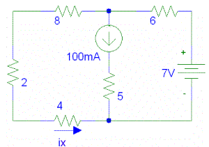
Example 2: Solve for the current ix flowing right through the 4 ohm resistor using Mesh-Current Analysis.  Solution: Label each mesh with a mesh current. Then write the KVL equations for each pane. Note that we were forced to label the voltage over the current source (Vx) in order to write the voltage term there:
  19 I1 + Vx - 5 I2 =0 -5 I1 - Vx + 11 I2 + 7 =0
We now have an extra unknown (Vx), so we need another equation. It is found be relating the two mesh currents to the current source.
I1-I2 = 100 mA
Note that i1 is positive because it is in the same direction of the source. I2 is negative because it is in the opposite direction as the source.
Now solve the three equations in three unknowns. I1 is found to be -320mA. Since ix is in the opposite direction of i1, then ix = 320mA.
- Resistances in Series

Req = R1 + R2 + R3 +……+Rn
- Inductors in Series

Leq = L1 + L2 + L3 +……+Ln
- Capacitors in Series


Parallel Combinations of Elements
- Resistances in Parallel


- Inductors in Parallel


 Ceq = C1 + C2 + C3 +…..Cn
- Voltage across resistor R1

- Voltage across resistor R2
 Current Division in Parallel Circuit of Resistors: The current in any branch is equal to the ratio of opposite branch resistance to the total resistance value, multiplied by the total current in circuit.
- Current through the branch R1

- Current through the branch R2


V = i × Rsh
i =V / Rse


Comments
write a comment