
- Home/
- GATE ELECTRICAL/
- GATE EE/
- Article
Study notes on Symmetrical Component & Symmetrical Fault Analysis: Electrical Engineering
By BYJU'S Exam Prep
Updated on: September 25th, 2023

Symmetrical components and symmetrical fault analysis are fundamental tools used in power system analysis to understand and address faults and disturbances that occur in electrical networks. Symmetrical components provide a mathematical technique for simplifying the analysis of unbalanced conditions in power systems. Symmetrical fault analysis, on the other hand, focuses on the study of faults in power systems.
In this article, you will find the study notes on Symmetrical Component & Symmetrical Fault Analysis which will cover the topics such as Symmetrical Component, Positive -Negative- Zero Sequence Component, Three Phase Power in Terms of Symmetrical Components, Sequence Component, Sequence Impedance of transmission Line, Sequence Impedance of Synchronous Machines, Sequence Network of Synchronous Machine, Zero-Sequence Impedance of Transformer, Transient on a Transmission Line, Symmetrical Fault Analysis & Three Phase Fault Calculation.
Download GATE Electrical Engineering Revision Sheet and Formulae PDF
Symmetrical Components
A three-phase system is said to be symmetrical when the system viewed from any phase is similar. Thus, in a three-phase symmetrical system the self-impedance of all the three phases are equal and the mutual impedances, if any between the three phases are the same any three phase system having unbalanced phasor quantities can be represented in terms of three phase balanced phasor components as a combination of positive, negative and zero sequence component, which are as follows:
Va = Vao + Va1+ Va2
Vb = Vbo + Vb1+ Vb2
Vc = Vco + Vc1+ Vc2
Also Read: Component of Power System For Electrical Engineering
Positive Phase Sequence Components
It represents a set of balance phasors Va1, Vb1 & Vc1 These components have three phasors equal in magnitude displaced by 120o and having same phase sequence as original phasors.

Negative Phase Sequence Components
These components have three phasors Va2, Vb2 & Vc2 equal in magnitude displaced by 120o but having phase sequence opposite to original phasors. It represents a set of balanced phasors

Download Formulas for GATE Electrical Engineering – Signals and Systems PDF
Zero Sequence Components
These phasors Vao, Vbo & Vco are equal in magnitude and having zero phase displacement.
α operator = e+j120° = – 0.5 + j 0.866
α2 = e+j240° = – 0.5 – j 0.866
α3 = 1
α4 =α
1 + α + α2 = 0


![]()

In matrix form

Three Phase Power in Terms of Symmetrical Components
![]()
= sum of symmetrical components power
![]()
Sequence Impedance
The positive sequence impedance of an equipment is the impedance offered by the equipment to the flow of positive sequence current. similarly, the negative sequence or zero sequence impedance of the equipment is the impedance offered by the equipment to the flow of corresponding sequence current.
Sequence Impedance of a Transmission Line
Positive sequence impedance Z1 = Zs – Zm
Negative sequence impedance Z2 = Zs – Zm
Zero sequence impedance Z0 = Zs + 2Zm
where, Zs = Self-impedance per phase
Zm = Mutual impedances between phases
Sequence Impedance of Synchronous Machine
- Positive Sequence, Impedance Z1 Depending on the time interval of interest one of the three reactance may be used.
- For the sub transient interval, we use sub transient reactance Z1 = j Xd
- For the transient interval, we use the transient reactance Z’1 = j X’d
- If the steady state value is of interest we have Z1 = j Xd
- Negative Sequence Impedance
![]()
3. Zero Sequence Impedance (Z0) Zero sequence current are all in phase and therefore, do not reproduce any rotating field. The zero sequence impedance Z0 depends upon the type of grounding and the zero sequence impedance per phase of the generator.
Sequence Networks Equations
Sequence Network of Unloaded Alternator
- Positive Sequence Network

![]()
2. Negative Sequence Network

![]()
3.Zero Sequence Network


Download Formulas for GATE Electrical Engineering – Electrical Machines PDF
Sequence Impedance of Transformers
- Switch A is closed when primary winding is star connected with neutral grounded.
- Switch C is closed when primary winding is delta connected.
- Switch B is closed when secondary winding is star connected with neutral grounded.
- Switch D is closed when secondary winding is delta (∆) connected.

- Keep both A and C open if when primary winding is star connected with natural isolated (not grounded).
- Keep both B and D open if when secondary winding is star connected with natural isolated.
where Z0 = Zero sequence impedance of transformer.
Examples


Fault may occur at different points in power system.
Faults that occur on a power system are broadly classified as follows
Transient on a Transmission Line
When a sudden change in voltage and current distribution takes place, a power energy distribution also changes. But energy distribution is called transient phenomenon in power system.

The current after short circuit I(t) has components i.e.,
I = Is + It
Where, Is = Steady state value of current
It = Transient current

3-ϕ Sudden Short Circuit of an Unloaded Alternator
Whenever a three-phase short circuit occurs at the terminals of an alternator, the armature current suddenly increases to a large value and voltage across its terminals drops.

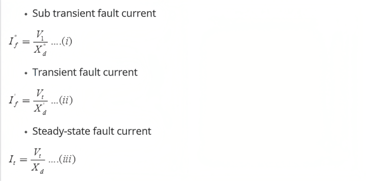
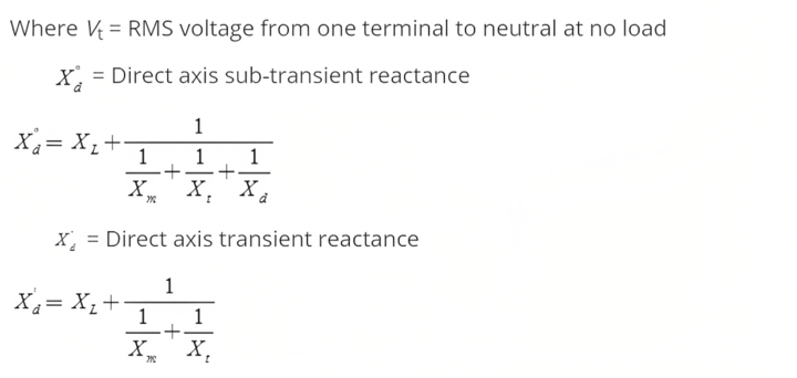
Xd = Direct axis synchronous reactance
Xd = XL + Xm
Where XL = Leakage reactance
Xm = Main winding reactance
Xt = Field winding reactance
Xd = Damper winding reactance
Note: ![]()
Symmetrical Fault Analysis
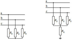
Three Phase Fault
Symmetrical short circuit on Synchronous Machine The selection of a circuit breaker for a power system depends not only upon the current the breaker is to carry under normal operating conditions but also upon the maximum current it may have to carry momentarily and the current it may have to interrupt at the voltage of the line in which it is placed.
In order to approach the problem of calculating the initial current, we need to study the behavior of a synchronous generator when it is short-circuited. When an ac voltage is applied suddenly across a series R-L circuit, the current which flows has two components 1.
a steady state sinusoidal varying component of constant amplitude and 2. a non-periodic and exponentially decaying with a time constant of L/R. (which is also referred as the dc component current).The initial value of the dc component of current depends on the magnitude of the ac voltage when the circuit is closed.
In such types of faults, all the three phases are short-circuited to each other and often to earth also. Such faults are balanced and symmetrical in the sense that the system remains balanced even after the fault.
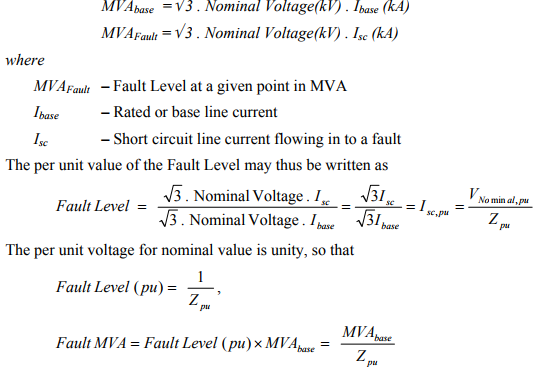
Fault Level Calculations
In a power system, the maximum fault current (or fault MVA) that can flow into a zero impedance fault is necessary to be known for switchgear solution. This can either be the balanced three phase value or the value at an asymmetrical condition.
The Fault Level defines the value for the symmetrical condition. The fault level is usually expressed in MVA (or corresponding per-unit value), with the maximum fault current value being converted using the nominal voltage rating.
The Short circuit capacity (SCC) of a busbar is the fault level of the busbar. The strength of a busbar (or the ability to maintain its voltage) is directly proportional to its SCC. An infinitely strong bus (or Infinite bus bar) has an infinite SCC, with a zero equivalent impedance and will maintain its voltage under all conditions.
Key Points
- Positive sequence currents are present in all types of faults.
- Negative sequence currents are present in all unsymmetrical faults.
- Zero sequence currents are present when the natural of the system is grounded and the fault also involves the ground and the magnitude of the natural current (In) is equal to 3Iao.
- Voltage of natural Vn = -InZn = -3IaoZn
- Shunt faults are characterized by increase in current and fall in voltage and frequency whereas series faults are characterized by increase in voltage and frequency and fall in current in the faulted phases.
Download Formulas for GATE Electrical Engineering – Signals and Systems
If you are preparing for GATE and ESE, avail Online Classroom Program to get unlimited access to all the live structured courses and mock tests from the following link:


