
- Home/
- GATE ELECTRICAL/
- GATE EE/
- Article
Combinational Circuits Study Notes for GATE Exams
By BYJU'S Exam Prep
Updated on: September 25th, 2023

Combinational circuits are an essential part of digital electronics. They are electronic circuits where the output depends solely on the current input states, and there is no feedback or memory element involved. These circuits perform specific logic operations, combining input signals to produce desired output results.
In this article, you will find the detailed study notes on Combinational Circuits which will cover the topics such as Introduction, Logic Gates and circuits, Logic Gates and their properties, Conversion of Logic Gates. Preparation with the Combinational Circuits notes will help you achieve good marks for the GATE, ISRO, ESE, SSC JE & other Electrical Engineering exams.
Download GATE Electrical Engineering Revision Sheet and Formulae PDF
Introduction to Combinational Circuit
Logic Circuits can be divided into two types.
- Combinational Logic Circuit, and
- Sequential Logic Circuit.
1. Combinational Logic Circuit
The combinational logic circuit contains the logic gates whose output is determined by the combination of current inputs.
- It comprises logic gates, input variables, and output variables.
- No feedback is required.
- No memory is required.

- Examples of combinational circuits are Encoder, Parallel Adders, Multiplexer, Decoder, , etc.
2. Sequential Logic Circuit
It contains the logic gates which are arranged in parallel and its output is determined by the combination of the current input and the prior output. The sequential circuit also consists of memory elements that are capable to store the information of the prior output.
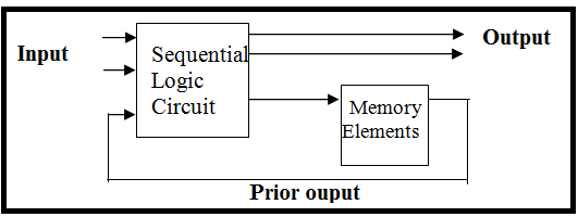
- Examples of sequential circuits are Counters, Flip-flops, Shift Registers, etc.
Download Formulas for GATE Electrical Engineering – Electrical Machines PDF
Logic Gates
A logic gate is a physical device implementing the Boolean function i.e. it is used to perform the logical operation for one or more logical inputs and produces a single logical output.
The logic gates can be classified as
- NOT, AND, OR, are basic gates.
- NAND, NOR are universal gates.
- EXOR, EXNOR is an arithmetic circuit which is also called comparators.
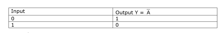
NOT Gate (Inverter)
Truth Table for NOT Gate:
Circuit Symbol for NOT Gate:

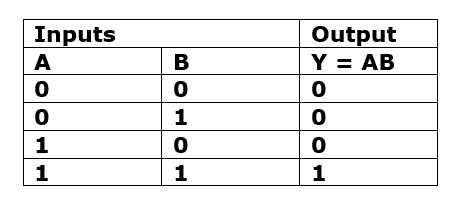
AND Gate
Truth Table for AND Gate:
Circuit Symbol for AND Gate:

Properties of AND logic:
- Commutative Law is expressed as AB = BA
- Associative Law is expressed as ABC = (AB) C = (AC)B = A(BC)
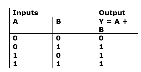
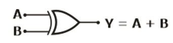
OR Gate
Truth Table:
Circuit Symbol for OR Gate:
Properties of OR logic:
- Commutative Law is expressed as A + B = B + A
- Associative Law is expressed as (A + B + C) = (A + B) + C = A + (B+ C)
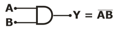
NAND Gate
Truth Table:

Circuit Symbol for NAND Gate:
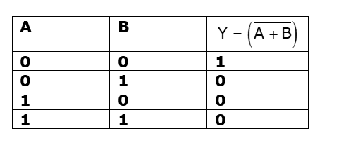
NOR Gate
Truth Table:
Circuit Symbol for NOR Gate:
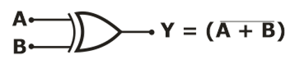
- NOR gates tries to follow commutative law whereas it doesn’t follow associative law
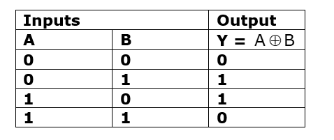
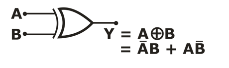
EXOR Gate
Truth Table:
Circuit Symbol for EXOR Gate:
Properties of EXOR Logic:
- Enable input = 0
- Disable input = 1
- It is also called stair case switch.
- It is mostly used in detection and parity generation.
- If both the inputs are different, then output comes out to be high or logic 1.
- If both the inputs are same, then output comes out to be low or logic 0.
Note:
![]()
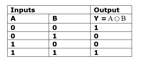
EX-NOR Gate
Truth Table:
Circuit Symbol for EX-NOR Gate:

Properties of EXNOR Gate:
- Enable input = 1
- Disable input = 0
- If both the inputs are the same, then output comes out to be high or logic 1.
- If both the inputs are different, then output comes out to be low or logic 0.
Logic Gate Conversions
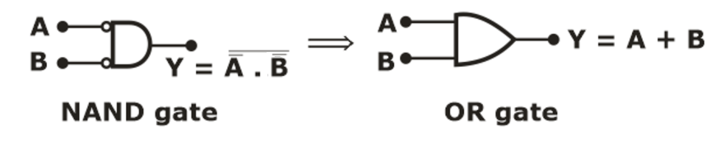
- OR Gate using NAND Gate:
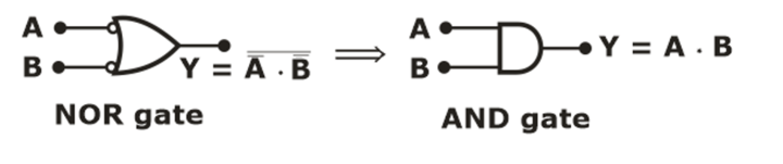
- AND Gate using NOR Gate:
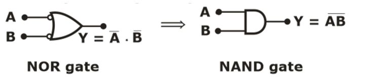
- NAND Gate using NOR Gate
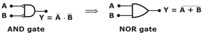
- NOR Gate using AND Gate
NAND and NOR Gate as Universal Gate
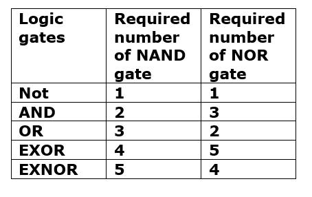
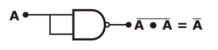
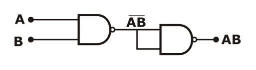
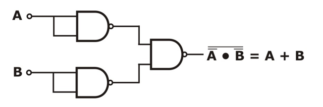
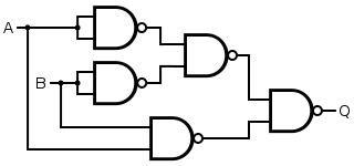
Designing different gates using NAND Gate as Universal Gate:
(i) NOT Gate:
(ii) AND Gate:
(iii) OR Gate:
(iv) EXOR Gate:
Download Formulas for GATE Electrical Engineering – Signals and Systems PDF
If you are preparing for GATE and ESE, avail Online Classroom Program to get unlimited access to all the live structured courses and mock tests from the following link:


