
- Home/
- GATE ELECTRICAL/
- GATE EE/
- Article
Time Domain Analysis Study notes Part-2
By BYJU'S Exam Prep
Updated on: September 25th, 2023

In this continuation of our comprehensive series, we delve even deeper into the fundamental concepts and techniques of time domain analysis. Understanding the behaviour of signals and systems in the time domain is essential for engineers, scientists, and enthusiasts working with various applications, such as control systems, communication systems, and signal processing. Building upon the foundation laid in Part 1, these notes will provide you with a more advanced and in-depth exploration of time-domain analysis, equipping you with the tools to analyze, model, and interpret complex time-domain signals and system responses.
We embark on a journey to explore advanced topics like transient and steady-state analysis, convolution, and impulse response. Moreover, we will introduce you to the concept of Fourier series and Fourier transforms, which play a crucial role in transforming time-domain signals into the frequency domain, opening up a new dimension of analysis. Whether you are a student seeking a clear understanding of time domain analysis or a professional looking to enhance your knowledge, these study notes will serve as an invaluable resource to deepen your expertise in this fascinating field. Let’s dive in and unravel the mysteries of time-domain signals and systems.
Download Formulas for GATE Electrical Engineering – Electrical Machines
Table of content
Time Domain Characteristics
In specifying the Transient-Response characteristics of a control system to a unit step input, we usually specify the following:
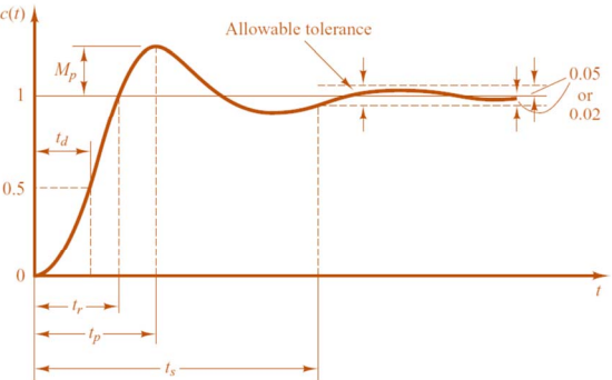
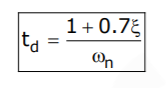
- Delay time ( td ): It is the time required for the response to reach 50% of the final value in the first attempt.
The expression of delay time, td for the second order system is:
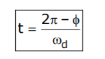
- Rise time, ( tr ): It is the time required for the response to rise from 0 to 100% of the final value for the under-damped system.
The expression of rise time, tr for second order system is:
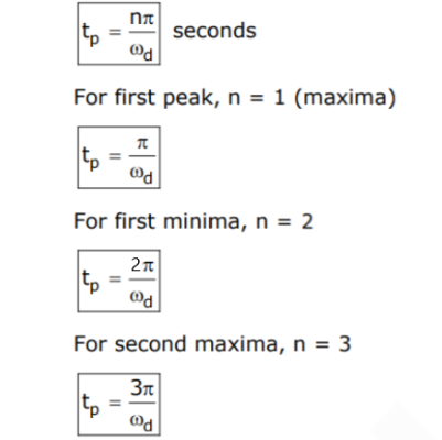
- Peak time, ( tp ): It is the time required for the response to reach the peak of time response or the peak overshoot.
The expression of peak time, tp for second order system is:
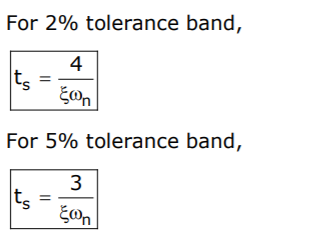
- Settling time, ( ts ): It is the time required for the response to reach and stay within a specified tolerance band ( 2% or 5%) of its final value.
The expression of settling time, ts for second order system is:
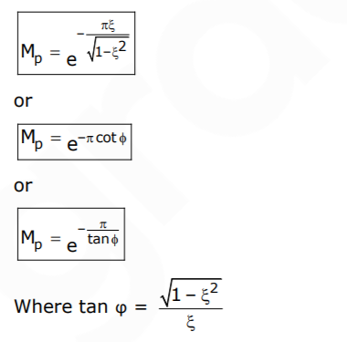
- Peak overshoot ( Mp): It is the normalized difference between the time response peak and the steady output and is defined as
![]()
The expression of peak overshoot, Mp for the second-order system is:
- Steady-state error ( ess ): It indicates the error between the actual output and desired output as ‘t’ tends to infinity.
![]()
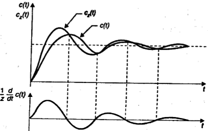
Effect of Adding a Zero to a System
If we add a zero at s = -z be added to a second order system. Then we have,
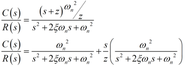
- The multiplication term is adjusted to make the steady-state gain of the system unity.
Manipulation of the above equation gives,
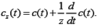
- The effect of the added derivative term is to produce a pronounced early peak in the system response.
- The closer the zero to the origin, the more pronounced the peaking phenomenon.
- Due to this fact, the zeros on the real axis near the origin are generally avoided in design. However, in a sluggish system, the artful introduction of a zero at the proper position can improve the transient response.
Types of Feedback Control Systems:
The open-loop transfer function of a system can be written as
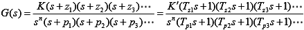
- If n = 0, the system is called a type-0 system, if n = 1, the system is called a type-1 system, if n = 2, the system is called a type-2 system, etc.
Steady-State Error and Error Constants:
The steady-state performance of a stable control system is generally judged by its steady-state error to step, ramp and parabolic inputs. For a unity feedback system,
![]()
Where,
E(s) is an error signal
R(s) is the input signal
G(s) H(s) is the open loop transfer function
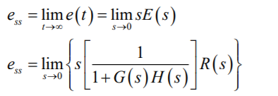
It is seen that steady-state error depends upon the input R(s) and the forward transfer function G(s).
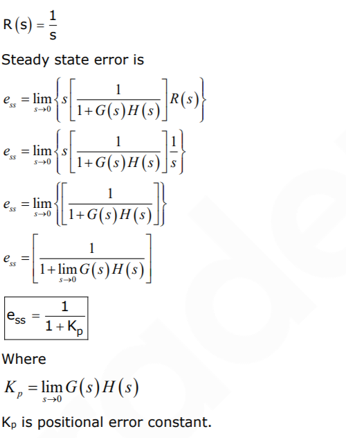
1. If input is unit step i.e R(t) = u(t)
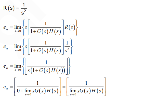
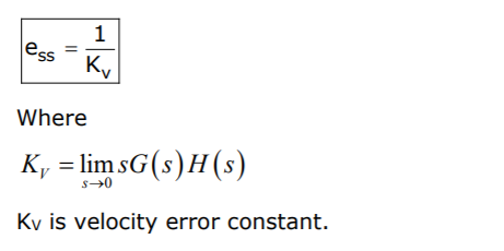
2. If input is unit ramp i.e R(t) = tu(t)
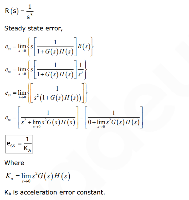
3. If input is unit parabolic i.e R(t) = 0.5tu(t)
If you aiming to crack GATE & ESE, Other PSU Exams then you must try Online Classroom Program to get unlimited access to all the live structured courses and unlimited mock tests from the following links:
ESE and GATE EC Online Classroom Program (24+ LIVE Courses and 150+ Mock Tests)
ESE and GATE EE Online Classroom Program (24+ LIVE Courses and 193+ Mock Tests)
Click on the Links Below to Avail Test Series:
Click Here to Avail GATE/ESE EC Test Series !!! (150+ Mock Tests)
Click Here to Avail GATE/ESE EE Test Series !!! (193+ Mock Tests)
Get complete information about the GATE exam pattern, cut-off, and all those related things on the BYJU’S Exam Prep official youtube channel.


