
- Home/
- GATE ELECTRICAL/
- GATE EE/
- Article
Network Theorems Part-1
By BYJU'S Exam Prep
Updated on: September 25th, 2023

Network theorems are fundamental principles in electrical engineering and circuit analysis that help simplify and analyze complex electrical networks. These theorems provide mathematical tools and techniques to determine various circuit parameters, such as current, voltage, power, and resistance.
In this article, you will find the study notes on Network Theorems & Transformation which will cover the topics such as Super Position Theorem, Thevenin’s Theorem, Norton’s Theorem & Millman’s Theorem & Maximum Power Transfer Theorem.
Table of content
What are the Network Theorems?
The fundamental theory on which many branches of electrical engineering, such as electric power, electric machines, control, electronics, computers, communications, and instrumentation, are built is the Electric circuit theory. So here, the network theorem helps us to solve any complex network for a given condition.
Note: All the theorems apply only to Linear networks; according to the theory of Linear Networks, they follow the condition of Homogeneity & Additivity.
Network Theory Principles
Here, a few principles of the concept of network theory are discussed in detail. Students can follow these principles for more information about network theory.
Homogeneity Principle
A system is said to be homogeneous, for any input signal x(t)
If input x(t) gives → response y(t)
then, it must follow ⇔ k x(t) →k y(t)
i.e. scaling in any input signal scales the output signal by the same factor.
Additivity Principle
A system is said to be homogeneous, for any input signal x(t)
If two input x1(t)+ x2 (t) ⇔ y1(t) + y2(t)
then, k1x1(t) + k2x2 (t) ⇔ k1 y1(t) + k2 y2(t)
i.e. the output corresponding to the sum of any two inputs is the sum of their respective outputs.
Superposition Theorem
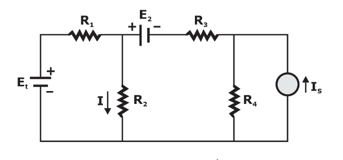
The superposition theorem finds use in solving a network where two or more sources are present and connected not in series or in parallel.
The superposition theorem states that if a number of voltage or current sources are acting simultaneously in a linear bidirectional network, the resultant response in any branch is the algebraic sum of the responses that would be produced in it when each source acts alone replacing all other independent sources by their internal resistances.
Procedure for using the superposition theorem
Step-1: Retain one source at a time in the circuit and replace all other sources with their internal resistances.
Step-2: Determine the output (current or voltage) due to the single source acting alone.
Step-3: Repeat steps 1 and 2 for each of the other independent sources.
Step-4: Find the total contribution by adding algebraically all the contributions due to the independent sources.
So for the above-given circuit the total response or say current I through resistor R2 will be equal to the sum of individual responses obtained by each source.
![]()
Removing of Active Element in Superposition Theorem
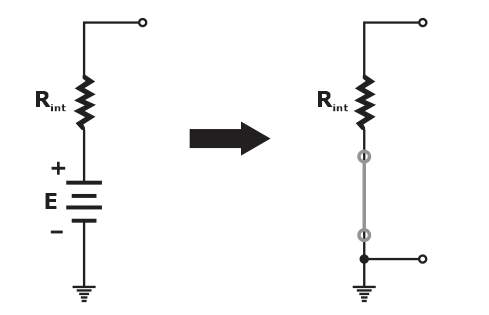
1. Ideal voltage source is replaced by the short circuit.
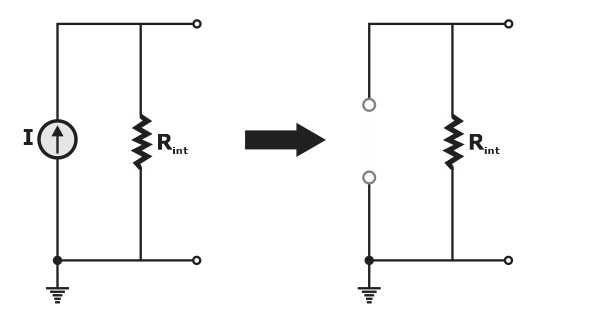
2. Ideal current source is replaced by an open circuit.
Limitation: Superposition cannot be applied to power calculation because the power is related to the square of the voltage across a resistor or the current through a resistor. The squared term results in a non-linear (a curve, not a straight line) relationship between the power and the determining current or voltage.
Thevenin’s Theorem
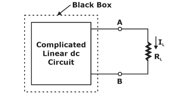
Thevenin’s theorem states that any two output terminals of an active linear network containing independent sources (it includes voltage and current sources) can be replaced by a simple voltage source of magnitude VTH in series with a single resistor RTH where RTH is the equivalent resistance of the network when looking from the output terminals A & B with all sources (voltage and current) removed and replaced by their internal resistances and the magnitude of VTH is equal to the open circuit voltage across the A & B terminals.
The procedure for applying Thevenin’s theorem
To find a current IL through the load resistance RL using Thevenin’s theorem, the following steps are followed:
Step-1: Disconnect the load resistance ( RL) from the circuit,
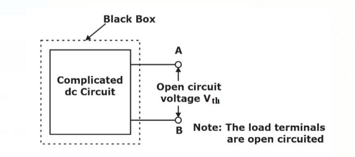
Step-2: Calculate the open-circuit voltage VTH at the load terminals (A & B) after disconnecting the load resistance ( RL ).
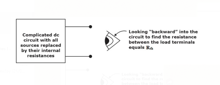
Step-3: Redraw the circuit with each independent source replaced by its internal resistance.
Note: Voltage sources should be short-circuited and current sources should be open-circuited.
Step-4: Look backward into the resulting circuit from the load terminals (A & B). Calculate the resistance that would exist between the
load terminals.
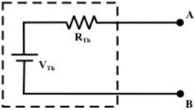
Step-5: Place RTH in series with VTH to form Thevenin’s equivalent circuit.
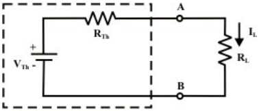
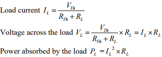
Step-6: Reconnect the original load to the Thevenin equivalent circuit as shown in the load’s voltage, current and power may be calculated by a simple arithmetic operation only.
Norton’s Theorem
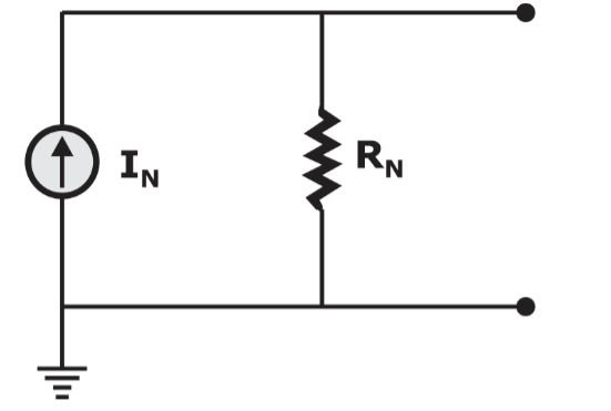
Norton’s theorem states that any two output terminals of an active linear network containing independent sources (it includes voltage and current sources) can be replaced by a current source and a parallel resistor RN. Where, RN which is the equivalent resistance of the network when looking from the output terminals A & B with all sources (voltage and current) removed and replaced by their internal resistances and the magnitude of IN is equal to the short-circuit current across the A & B load terminals.
Norton Equivalent Circuit can be shown as
Maximum Power Transfer Theorem
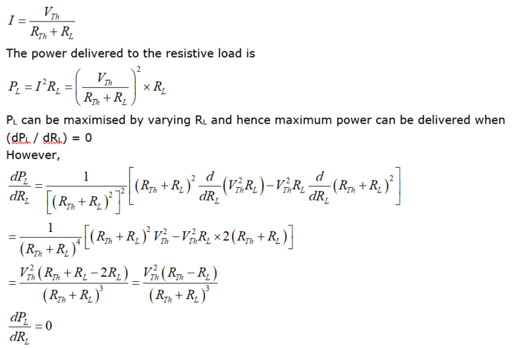
Maximum Power Transfer Theorem states a resistive load, being connected to a DC network, consumes maximum power when the load resistance is equal to the thevenin’s equivalent resistance of the source network as seen from the load terminals.
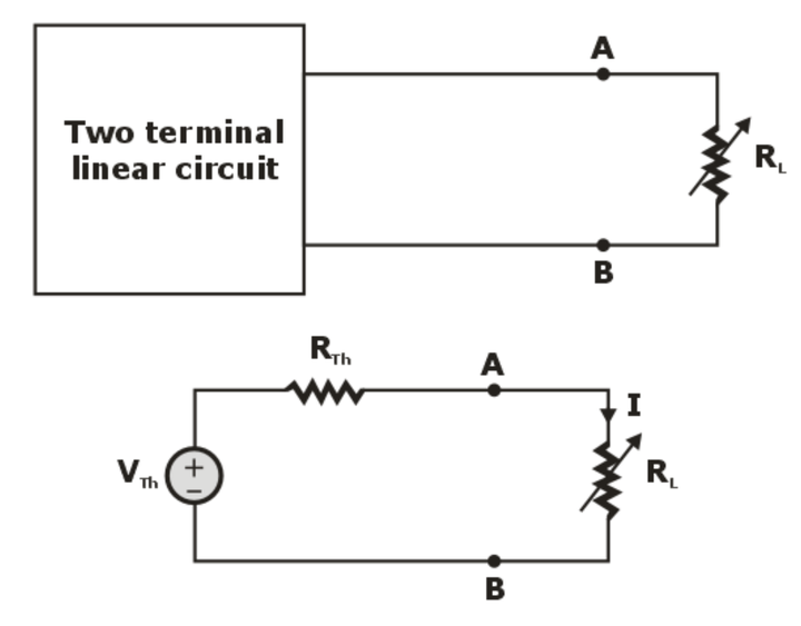
A variable resistance RL is connected to a dc source network as shown in the figure above and the Thevenin’s voltage VTh and Thevenin’s equivalent resistance RTh of the source network. The aim is to determine the value of RL such that it consumes maximum power from the DC source.
Steps for Solution of a Network Using Maximum Power Transfer Theorem
Step 1: Remove the load resistance and find Thevenin’s resistance (RTh) of the source network by looking through the open-circuited load terminals.
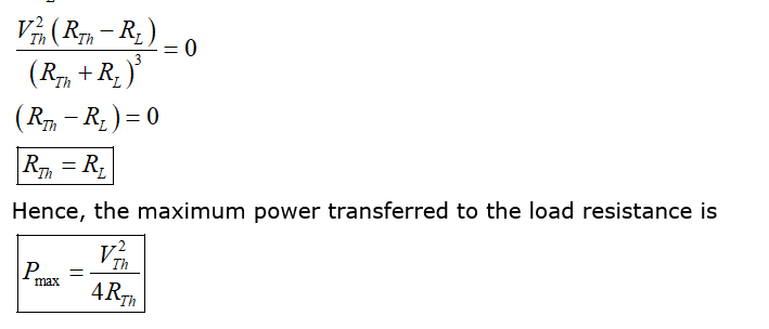
Step 2: As per the maximum power transfer theorem, this RTh is the load resistance of the network i.e. RL = RTh that allows maximum power transfer.
Step 3: Find Thevenin’s voltage (VTh) across the open-circuited load terminals.
Step 4: Maximum Power Transfer is given by:
Pmax = (Vth)2/ 4Rth
Note: Maximum power transfer condition results in 50 percent efficiency in Thevenin equivalent, however much lower efficiency in the original circuit.


