
- Home/
- GATE ELECTRICAL/
- GATE EE/
- Article
Graph Theory Study Notes for Electrical Engineering
By BYJU'S Exam Prep
Updated on: September 25th, 2023

In this article, you will find the Study Notes on Graph Theory which will cover the topics such as Graph, Component of Graph & Types of Graph, Tree-CoTree & Matrix Representation of Graphs.
1. Graph :
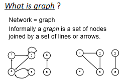
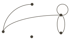
Conceptually, a graph is formed by vertices and edges connecting the vertices. a graph G is a pair of sets (V, E), where V is the set of vertices and E is the set of edges, formed by pairs of vertices.
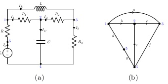
From a circuit to its graph: There is a node exist b/w two elements of a circuit. All the active source are represented by its internal impedance characteristic.
hence graph for a given network such as
Directed (or Oriented) graph: A graph is said to be directed (or oriented) when all the nodes and branches are numbered or direction assigned to the branches by an arrow. As shown in above graph.
2. COMPONENT OF GRAPH
(i) Vertices or Vertex: Basic Element of Graph, Drawn as a node or a dot.Vertex set of G is usually denoted by V(G), or V.
(ii) Edge: A set of two elements, Drawn as a line connecting two vertices, called end vertices, or endpoints.The edge set of G is usually denoted by E(G), or E.
Example:
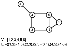
(iii) Degree of a Graph: Number of edges incident on a node. As the graph is shown above the degree of node 5 is 3.
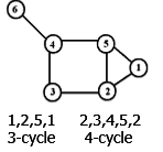
(iv) Path & Cycle: A path is a walk in which all the edges and all the nodes are different, while a cycle is a closed path in which all the edges are different.
(v) Empty Graph / Edgeless graph : No edge.
(vi) Null Graph: Obviously graph having no edge & no vertices.
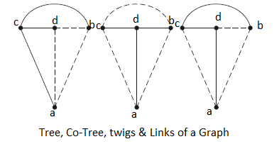
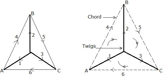
(vii) Trees: It is an interconnected open set of branches which include all the nodes of the given graph. In a tree of the graph, there can’t be any closed loop.
(viii) Co Tree: The different types of an interconnected open set of original tree named as co-tree.
(ix) Tree branch(Twig): It is the branch of a tree. It is also named as twigs. Represented by a continuous line in a tree.
(x) Tree link(or chord): It is the branch of a graph that does not belong to the particular tree. Represented by hashed line in a tree.
Relation between twigs and links-
{ L= B-(N-1) } { No. of twigs= N-1 }
N=no. of nodes L= total no. of links B= total no. of branches
![]() where [A] Reduced incident Matrix, obtained by eliminating any one row of incident Matrix.
where [A] Reduced incident Matrix, obtained by eliminating any one row of incident Matrix.
Properties of a Tree-
(a) It consists of all the nodes of the graph.
(b) If the graph has N nodes, then the tree has (N-1) branch.
(c) There will be no closed path in a tree.
(d) There can be many possible different trees for a given graph depending on the no. of nodes and branches.
(xi) Directed (or Oriented) graph: A graph is said to be directed (or oriented ) when all the nodes and branches are numbered or direction assigned to the branches by an arrow.
(xii) Connected Graph: When at least one path along branches between every pair of a graph exists, it is called a connected graph.
(xiii) Sub graph: A graph said to be sub-graph of a graph G if every node of is a node of G and every branch of is also a branch of G.
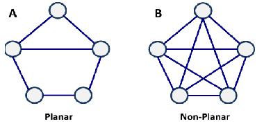
(xiv) Planer & Non-Planer graph: Graph A is planar since no link is overlapping with another. Graph B is non-planar since many links are overlapping.
3. Matrices in Graph Theory
1-INCIDENCE MATRIX:
(a)This matrix shows which branch is incident to which node.
(b)Each row of the matrix being representing the corresponding node of the graph.
(c)Each column corresponds to a branch.
(d)If a graph contains N- nodes and B branches then the size of the incidence matrix [A] will be NXB.
Procedure:
(a) If the branch j is incident at the node I and oriented away from the node, =1. In other words, when =1, branch j leaves away node i.
(b) If branch j is incident at node j and is oriented towards node i, =-1. In other words, j enters node i.
(c) If branch j is not incident at node i. =0. The complete set of incidence matrix is called augmented incidence matrix.
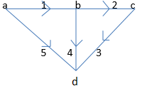
Example 1: Obtain the incidence matrix of the following graph.
Solution:
Node-a:- Branches connected are 1 & 5 and both are away from the node.
Node-b:- Branches incident at this node are 1,2 & 4. Here branch is oriented towards the node whereas branches 2 & 4 are directed away from the node.
Node-c:- Branches 2 & 3 are incident on this node. Here, branch 2 is oriented towards the node whereas the branch 3 is directed away from the node.
Node-d:- Branch 3, 4 & 5 are incident on the node. Here all the branches are directed towards the node.
so Node↓/Branch→ 1 2 3 4 5
a 1 0 0 0 1
[Ai] = b -1 1 0 1 0 where Ai is the Incidence Matrix.
c 0 -1 1 0 0
d 0 0 -1 -1 -1
Properties:
(i) The Algebraic sum of the column entries of an incidence matrix is zero.
(ii) The determinant of the incidence matrix of a closed loop is zero.
Reduced Incidence Matrix: If any row of a matrix is completely deleted, then the remaining matrix is known as reduced Incidence matrix. For the above example, after deleting any one row, we get
Node↓/Branch→ 1 2 3 4 5
a 1 0 0 0 1
[A] = b -1 1 0 1 0 where A is the Reduced Incidence Matrix.
c 0 -1 1 0 0

2. Tie Set Matrix :
A fundamental tie-set of a graph w.r.t a tree is a loop formed by only one link associated with other twigs.No. of fundamental loops=No. of links=B-(N-1).
The procedure of obtaining Tie-set matrix:
(i) Arbitrarily a tree is selected in the graph.
(ii) From fundamental loops with each link in the graph for the entire tree.
(iii)Assume directions of loop currents oriented in the same direction as that of the link.
(iv) From fundamental tie-set matrix [bij] where
[bij] = 1; when branch bj is in the fundamental loop i and their reference directions are oriented same.
[bij] = -1; when branchbj is in the fundamental loop i but, their reference directions are oriented oppositely.
[bij] = 0; when branchbj is not in the fundamental loop i .
Example 2 Draw the graph and write down the tie-set matrix. Obtain the network equilibrium equations in matrix form using KVL.
Tie-Set Matrix Formation:
| Brach Current ↓ / Branch → | 1 | 2 | 3 | 4 | 5 | 6 |
| i1 | +1 | -1 | 0 | +1 | 0 | 0 |
| i2 | 0 | 1 | -1 | 0 | 1 | 0 |
| i3 | -1 | 0 | 1 | 0 | 0 | 1 |
So, KVL equation ⇒ V1-V2+V4= 0, V2-V3+V5=0
Tie-Set Matrix is also Called Fundamental Loop Matrix
3.Cut-Set Matrix
The fundamental cut set is a cut through a given graph which divides into two parts but in its path of cutting it should encounter only one twig. The path of cut set forms a voltage line, it is called as cut set voltage. The orientation of this cut–set voltage is given by the twig governing it.
The number of cut set for any graph = n – 1 = number of twigs.
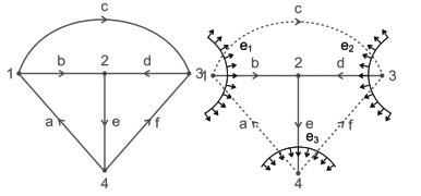
here b, d, e forms as tree
b, d, e → twigs
a, c, f → Links
Number of fundamental cut sets = 4 – 1 = 3
Fundamental cut set 1 is a, b, c with b as a twig and a, c, as links e1 is cut set voltage and the direction is same as twig ‘b’.
Similarly cut set 2 → c, d, f → cut set voltage e2
cut set 3 → a, e, f → cut set voltage e3
Cut Set Matrix gives the relation between cut set voltages and branch voltages The rows of a matrix represent the cut set voltages. The columns of a matrix represent the branches of the graph. The order of the cut set matrix is (n – 1) × b. The elements of a cut set matrix, [c] =[aij] n−1×b [aij] = +1, If jth branch is incident to
The columns of a matrix represent the branches of the graph. The order of the cut set matrix is (n – 1) × b.
[aij] = +1, If the jth branch is incident to ith cut set and oriented in the same direction.
[aij] = –1, If the jth branch is incident to ith cut set oriented in opposite direction.
[aij] = 0, If the jth branch is not incident with ith cut set voltage.
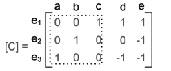
Example 3: For the network graph below construct the cut set matrix and write the equilibrium equations by considering branches a, b, c as tree branches.
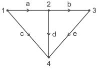
solution:
a, b, c → twigs
d, e → Links
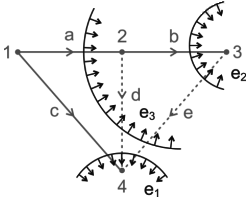
Fundamental cut set 1→ c d e → cut set voltage e1
Fundamental cut set 2 → b e → cut set voltage e2
Fundamental cut set 3 → a d e → cut set voltage e3
Cut Set Matrix
Let ja, jb, jc, jd, je be the branch currents, then
jc + jd + je = 0
jb – je = 0
ja – jd – je = 0
let va, vb, vc, vd, ve be the branch voltages, then
va = e3; vd = e1 − e3; vb = e2; ve = e1 − e2 − e3; vc = e1,


