
- Home/
- GATE ELECTRICAL/
- GATE EE/
- Article
Sequential Circuits-2 Study Notes for EE/EC
By BYJU'S Exam Prep
Updated on: September 25th, 2023

In this article, you will find the Study Notes on Sequential Circuits-2 which will cover the topics such as Registers, Counters, Classification of counters, Asynchronous and Synchronous Counters, FSMs.
Download Formulas for GATE Electrical Engineering – Signals and Systems
Table of content
Registers
When a group of the flip flop is used to store a word ( a group of bits) then it is called a register. To store n bits, n flip flops are cascaded in the register. If in a register, the binary information can be moved from stage to stage, this type of register is called a shift register. According to data movement in a register, shift registers can be classified as
- Serial Input Serial Output (SISO)
- Serial Input Parallel Output (SIPO)
- Parallel Input Serial Output (PISO)
- Parallel Input Parallel Output (PIPO)
Formulas for GATE Electrical Engineering – Electromagnetic Theory
Serial Input Serial Output (SISO)
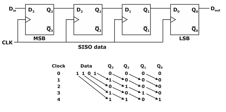
- In registers edge, trigger circuit is used to make the circuit synchronous.
- If no clock is applied then get the same data which is stored.
- In N bits SISO registers to provide N bits data, Serially in require an N clock pulse, and Serially out require an (N-1) clock pulse.
Formulas for GATE Electrical Engineering – Electrical Machines
Serial Input Parallel Output (SIPO)
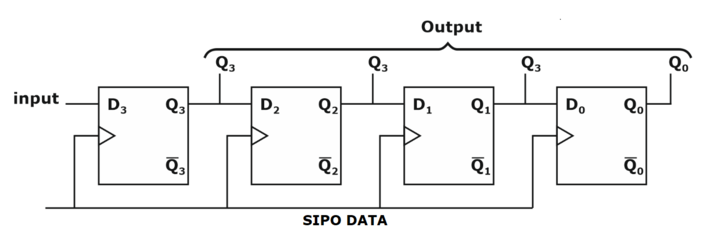
- To provide N-bit data: Serial in requires an N clock pulse, and Parallel out requires no clock pulse.
- SIPO can provide n × tCIK delay to the input.
- SIPO can convert serial data or temporal code to parallel or serial code.
Parallel Input Serial Output (PISO)

- If control = 0 then it acts as parallel input;
- If control = 1 then it acts as serial output;
- To provide parallel input, one clock pulse is required.
- To provide N bits serial output, it requires (N-1) clock pulse.
- PISO can convert special code to temporal code.
Parallel Input Parallel Output (PIPO)
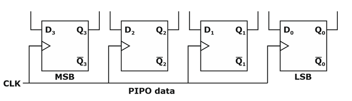
- In PIPO register for parallel input number of pulse required is 1 clock pulse.
- In PIPO register for parallel output number of pulse required is 0 clock pulse.
- PIPO register cannot be used as a shift register.
- It is used for temporal storage of data in microcontroller, DSP, CPU etc.
Summary of Registers

Counter
- A counter is a sequential logic circuit capable of counting the number of clock pulses arriving at its clock input.
- The sequence of count may be ascending, descending or non-sequence.
- For a counter circuit having n flip flops, Maximum possible states (N) = 2n
- If N = 2n, the counter acts as a binary counter.
- If N < 2n, the counter is the non-binary counter.
- Its counter is capable to count from 0 to 2n-1.
- The MOD number is the Number of states present in a counter is known as modulus count or MOD number.
- For n-flip flops, the counter will have 2n different states then this counter is said MOD- 2n counter.
MOD-N Counter
- The MOD number indicates frequency division obtained from the last flip flops.
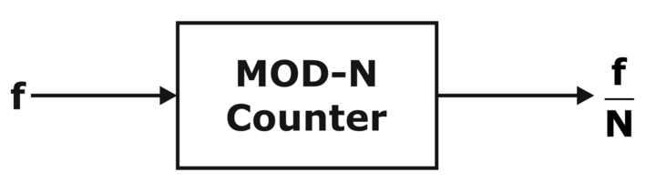
- Cascaded two counters:
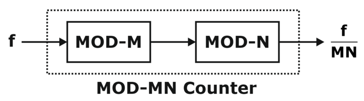
- MOD-MN counter:
- Overall states of combined counter = MN
- Input frequency = f
- Output frequency f = f/(MN)
Classification of Counters
Based on the application clock pulse, counters are classified into two categories.
- Synchronous counter
- Asynchronous counter (ripple counter)

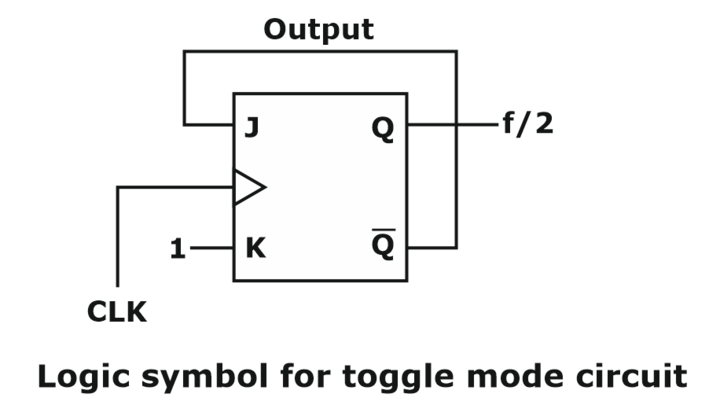
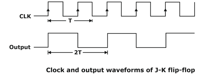
Toggle Mode Circuit
These are frequency divider circuits.
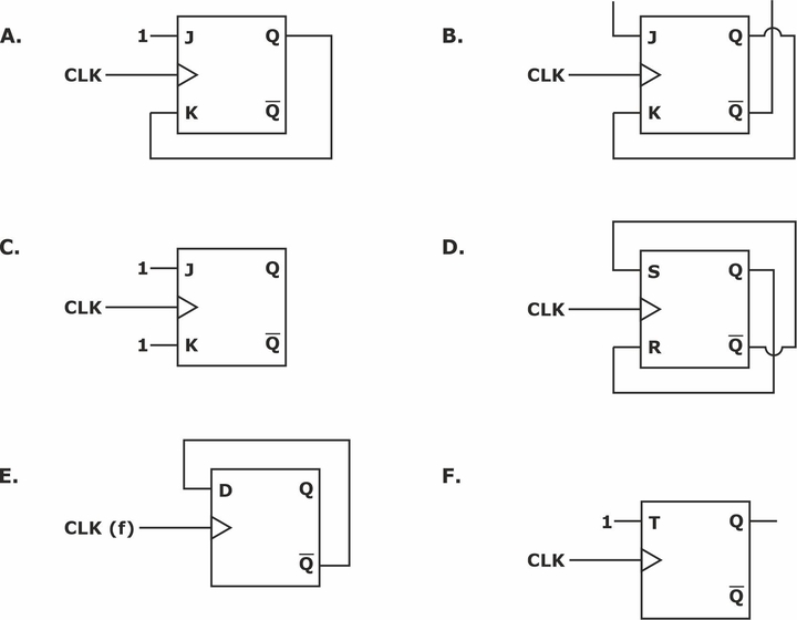
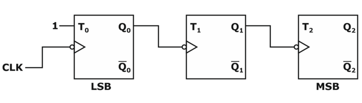
Other Toggle Mode Circuit
Asynchronous Counter (Ripple counter)
- A different clock pulse is applied to different flip-flops.
- All flip-flops are operating in toggle mode.
- In the asynchronous counter flip flop applied with an external clock acts as an LSB bit.
3-bit Ripple Up Counter
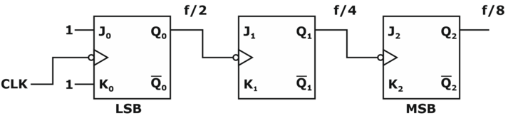
- The input clock is applied at the LSB bit.
- Its n-bit ripple counter maximum possible states are 2n.
- Bit ripple-up counter counts from 0 to 2n – 1.
- If all states are used then with input frequency f, the output frequency will be f/2n
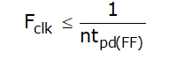
- Calculation of Time Period of Flip Flop: In the n-bit ripple counter if the propagation delay of each flip flop is tpd(FF), then the time period of the clock is:
![]()
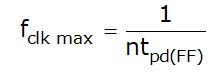
- Maximum Clock Frequency:
- Due to propagation delays of flip flops decoding errors are present.
- Clear and preset are known as asynchronous input to flip-flop.
- In any ripple counter, the following conditions will fulfil
- Negative edge trigger and Q as clock ⇒ up counter
- Positive edge trigger and Q as clock ⇒ up counter
3-bit Ripple Down Counter
- Positive edge trigger and Q as clock ⇒ down counter
- Negative edge trigger and Q as clock ⇒ down counter
Non-binary Ripple Counter
A decode counter or BCD counter is an example of a non-binary counter. It requires 4 flip flops.
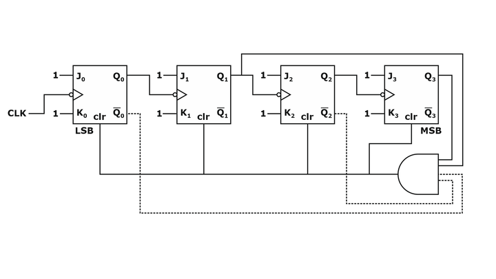
- Used state = 10 and unused states = 6 → (24 -10)
- Output frequency of BCD counter = f/10
- For making a non-binary counter clear (clr) signal is used.
- c1r is active high, and (clr)’ is active low.
Synchronous Counters
In this type of counter, there are no connections between the first flip-flop output to the clock input of the next flip-flop.
Ring Counter: It is a circular shift register with only flip flop being set at any particular time, all others are cleared. It is a shift register with feedback.
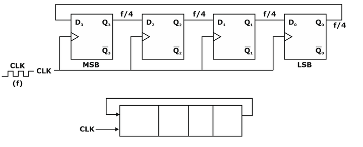
- In ring counter, if feedback is used the number of states is reduced.
- With n flip flops maximum states = n.
- Number of unused states in ring counter = 2n – n
- Maximum Clock Frequency: If the input frequency is f, then at the output of every flip flop we get f/N frequency. In-ring counter, if the propagation delay of each flip flop is tpd(FF) then
![]()
![]()
Jhonson Ring Counter: Jhonson ring counter is also called as a Twisted ring counter, Switch tail counter, Creeping counter, or Mobies counter.
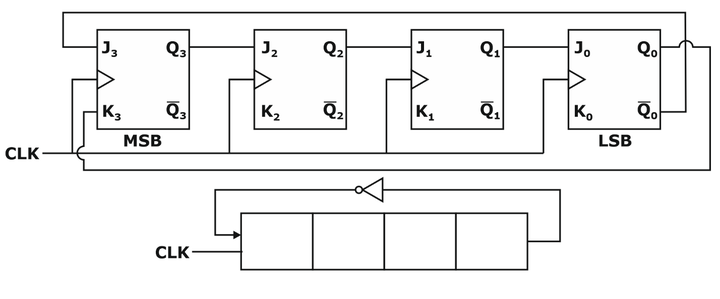
- In n – bit Jhonson counter maximum used states = 2n, unused states = 2n – 2n.
- If the input clock frequency is f, the output frequency of each flip flop is f /2n and the duty cycle is 50%.
- A disadvantage of the Jhonson Ring Counter: Lockout may occur. To decode each state one, or two input AND or NOR gate is used.
If you are preparing for GATE and ESE, avail of the Online Classroom Program to get unlimited access to all the live structured courses and mock tests from the following link :
ESE and GATE ECE Online Classroom Program (24+ Live classes and 150+ mock tests)
ESE and GATE EE Online Classroom Program (24+ Live classes and 193+ mock tests)
Get complete information about the GATE exam pattern, cut-off, and all those related things on the BYJU’S Exam Prep official youtube channel.


