
- Home/
- GATE ELECTRICAL/
- GATE EE/
- Article
Network Theorems & Transformations Study Notes Part-2
By BYJU'S Exam Prep
Updated on: September 25th, 2023

Network theory is a fundamental discipline in the field of electrical engineering and computer science that deals with the analysis and design of electrical circuits and communication systems. It provides a theoretical foundation for understanding the behavior and characteristics of various interconnected components and their interactions within a network. These short notes aim to provide a concise overview of key concepts and principles in network theory.
Network Theorems & Transformation study notes explained in Part-2 cover the topics such as Reciprocity Theorem, Tellegen’s Theorem, Millman’s Theorem, Substitution Theorem & Star-delta Transformation. These topics are important to be asked in the GATE, ISRO, SSC JE, ESE, and other Electrical Engineering exams.
Table of content
What is Millman’s Theorem?
Millman’s theorem helps to reduce the ‘N’ number of parallel voltage sources to one. For example, it can be observed in the given figure below. This technique permits finding the current through or voltage across RL without applying methods such as mesh analysis, nodal analysis, superposition, etc. For example, the given three voltage sources can be reduced to one voltage source.
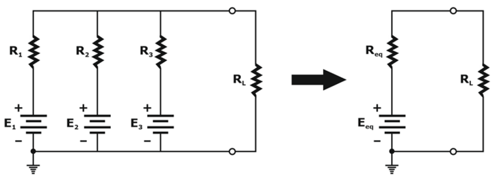
Generally, three steps are included in its application
Step 1: Convert all voltage sources into current sources.
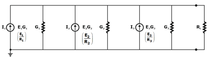
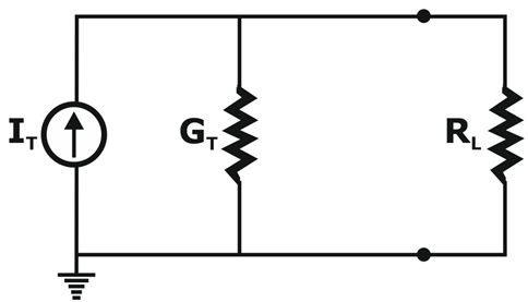
Step 2: Convert the parallel current source into the resulting network as shown below
IT= I1+I2+I3 & GT = G1+G2+G3
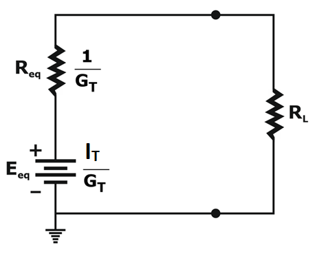
Step 3: Convert the resulting current source to a voltage source by transformation, and the desired single-source network will be shown as
![]()
![]()
Reciprocity Theorem
The reciprocity theorem applies to single-source networks only. The theorem states that the current I in any branch of a network due to a single voltage source E present anywhere else in the network will be equal to the current across the branch in which the source was originally placed if the source is placed in the branch in which the current I was originally(initially) measured.
In other words, the location of the voltage source and the resulting current may be interchanged without a change in the magnitude of the current. The theorem postulates that the polarity of the voltage source has the same adaptation with the direction of the branch current in each position.
Tellegen’s Theorem
- Tellegen’s theorem is based upon two of Kirchhoff’s laws. It is also applicable for any lumped network having elements that are linear or non-linear, active or passive, time-varying or time-invariant.
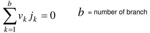
- For a lumped network whose element is assigned by associate reference direction for branch voltage vk and branch current jk. The product vkjk is the power delivered at time t by the network to the element k.
- If all branch voltages and branch currents satisfy KVL and KCL, then.
Application of Tellegen’s Theorem
As seen from the last equation, Tellegen’s Theorem implies the energy conservation law. The sum of power delivered by the independent sources to the network elements is equal to the sum of the power absorbed by all the network branches. So, the application of Tellegen’s theorem can be classified as
- Conservation of energy
- Conservation of complex power
- The real(or active) part and the phase of the driving point impedance
- Driving point impedance
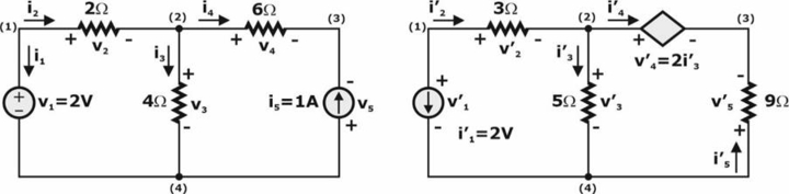
Example: Find all branch voltages and currents for networks N1 and N2, then verify Tellegen’s theorem.
Substitution Theorem
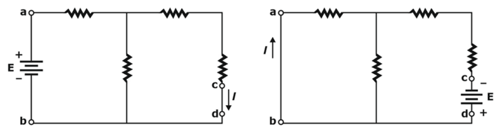
The substitution theorem states, If the voltage across any branch and the current flowing through that branch of a dc bilateral network are known, then that branch can be substituted by any one of the combinations that can consist of the same voltage and current through that chosen branch.
More simply, the theorem states that the voltage across the terminal and current through the terminal must be the same for branch equivalence. For example, consider the circuit where the voltage across and current through the branches a-b are determined. Then, a few equivalent a-a′ branches are shown using the substitution theorem. Note that for each equivalent circuit, the terminal voltage & the current remain the same.
- By the use of the substitution theorem, the number of equivalent branches is:
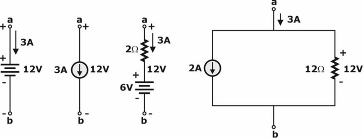
Note: for each equivalent, the terminal voltage and current are the same and known potential difference, and the current in a network can be replaced by an ideal voltage source and current source, respectively.
- Example: The current source equivalence where a known current is replaced by an ideal current source, permitting the isolation of R4 and R5 as shown below
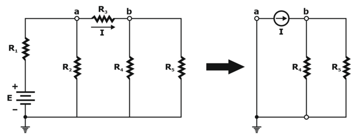
Recall the discussion of bridge networks that V = 0 and I = 0 were replaced by a short-circuit and an open circuit, respectively.
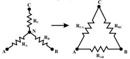
Star-Delta Transformation
A part of a bigger circuit that is configured with the three-terminal network Y (or Δ) has to be converted into an equivalent Δ (or Y) through transformations. Applications of these transformations will be studied by solving the resistive circuits.
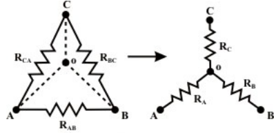
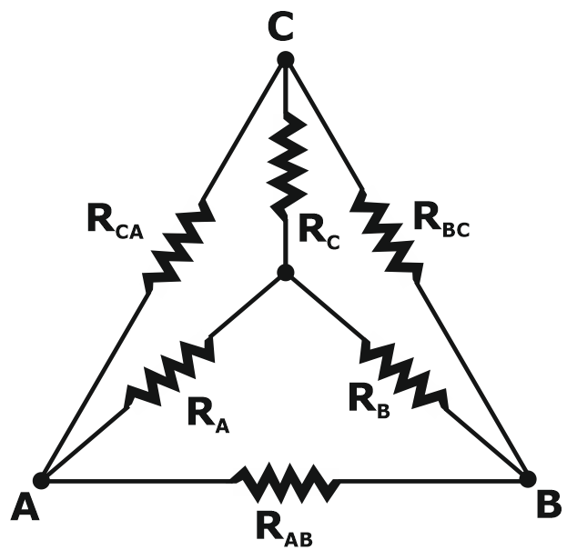
Delta (Δ) – Wye (Y) Conversion
Let us consider the network shown below and assume the resistances ( RAB, RBC, RCA) in Δ network are known. Now the requirement is to measure the resistance values of the branches of the Wye (Y) network that would produce the same resistances when measured across similar pairs of terminals of Δ network. For this, We have to write the equivalence resistance between any two terminals in the following form.
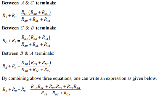
- On solving the above equations, we get values for star network resistances.
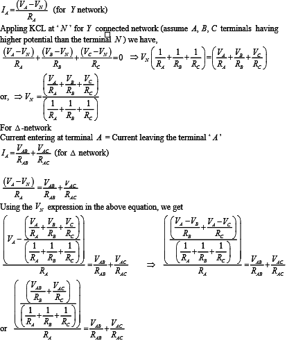
Conversion from Wye or Star (Y) to Delta (Δ)
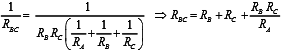
- To convert a Wye (Y ) to a Delta (Δ ), the relationships RAB, RBC & R3 must be obtained in terms of the Wye (Y) resistances RA RB and RC. Considering the Y-connected network, we can write the current expression through the RA resistor as
- After equating the coefficients of VAB and VAC on both sides, we get the following relationship.
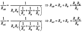
- Similarly, we can obtain RBC for an equivalent delta configuration
- Observations: With a view to the symmetry of the transformation equations, the Wye (Y) and Delta (Δ) networks have been superimposed on each other.
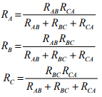
- The equivalent Wye (Y) resistance connected to a given terminal is equal to the product of the two Delta (Δ) resistances connected to that same terminal divided by the sum of all the Delta (Δ) resistances.
- The equivalent Delta (Δ) resistance between the two terminals is the product of the two-star (Y) resistances connected to those terminals divided by the third-star resistance plus the sum of the two same-star (Wye) resistances.
The network theorems and transformation explained in the 2nd part is an important chapter of the Network theory as it is most asked in the GATE EE, ESE EE, ISRO EE, and other electrical branch exams.


