- Home/
- GATE ELECTRICAL/
- GATE EE/
- Article
Timers and Filters Study Notes for Electrical Engineering
By BYJU'S Exam Prep
Updated on: September 25th, 2023

In this article, you will find the Study Notes on Timers and Filters which will cover the topics such as Voltage Controlled Oscillator and its types and applications, The 555 Timer IC and its various operating modes, Schmitt trigger, Sample and Hold circuits, Active and passive filters, types of filters and scaling.
1. Voltage Controlled Oscillator
- A Voltage Controlled Oscillator (VCO) is an oscillating circuit whose output frequency changes in direct proportion to an input voltage.
- VCOs can be made to oscillate from a few Hertz to hundreds of GHz.
- Every wireless device in use today has some sort of voltage controlled oscillator inside it.
- For example, there is a least one VCO inside every cell phone that generates the Radio Frequency (RF) waves that are used to communicate by-directionally to the cell tower.
- A Voltage controlled oscillator is an oscillator with an output signal whose output can be varied over a range, which is controlled by the input DC voltage.
- It is an oscillator whose output frequency is directly related to the voltage at its input.
- The oscillation frequency varies from few hertz to hundreds of GHz. By varying the input DC voltage, the output frequency of the signal produced is adjusted.
Types of Voltage Controlled Oscillators:
- Harmonic Oscillators: The output is a signal with a sinusoidal waveform. Examples are crystal oscillators and tank oscillators.
- Relaxation Oscillators: The output is a signal with saw tooth or triangular waveform and provides a wide range of operational frequencies. The output frequency depends on the time of charging and discharging of the capacitor.
- Applications of VCO:
- Electronic jamming equipment.
- Function generator.
- Production of electronic music (for the production of different types of noise).
- Phase locked loop.
- Frequency synthesizers, used in communication circuits.
2. The 555 Timer
- The 555 monolithic timing circuits is a highly stable device that can act either as a time delay generator (Monostable/one T shot), a Pulse-Width-Modulator (PWM), an RC Oscillator, or a Voltage Controlled Oscillator (VCO).
- In the time delay mode of operation, the time is precisely controlled by one external resistor and one external capacitor.
- For a stable operation as an oscillator, the free running frequency and the duty cycle are both accurately controlled with two external resistors and one external capacitor.
555 Pinout:
- Ground: Connect this to the ground. Remember to connect all grounds in a circuit together.
- Trigger: A short low (less than 1/3 Vcc) pulse on the trigger starts the timer. By connecting this to the ground we “turn on” the 555 timers.
- Output: During a timing interval, the output stays at +VCC. Can source up to 200ma.
- Reset: Forces pin 3 low if pulled to ground.
- Control: It Can be used to adjust threshold trigger voltage. Not used in our applications. Connect to the ground with a .01uF cap to eliminate supply noise from Vcc.
- Threshold: When threshold crosses above 2/3 Vcc timing interval end.
- Discharge: Connects to the ground when output goes low. Controls timing.
- Vcc: Power supply. Typical range 4.5v to 16v.
The 555 has three main operating modes, Monostable, Astable, and Bistable.
- Astable mode:
- An Astable Circuit has no stable state – hence the name “astable”.
- The output continually switches state between high and low without any intervention from the user, called a ‘square’ wave.
- This type of circuit could be used to give a mechanism intermittent motion by switching a motor on and off at regular intervals.
- It can also be used to flash lamps and LEDs and is useful as a ‘clock’ pulse for other digital ICs and circuits.
- Monostable mode:
- A Monostable Circuit produces one pulse of a set length in response to a trigger input such as a push button.
- The output of the circuit stays in the low state until there is a trigger input, hence the name “monostable” meaning “one stable state”.
- This type of circuit is ideal for use in a “push to operate” system for a model displayed at exhibitions.
- A visitor can push a button to start a model’s mechanism moving, and the mechanism will automatically switch off after a set time.
- Bistable Mode (or Schmitt Trigger):
- A Bistable Mode or what is sometimes called a Schmitt Trigger has two stable states, high and low.
- Taking the Trigger input low makes the output of the circuit go into the high state. T
- Taking the Reset input low makes the output of the circuit go into the low state.
- This type of circuit is ideal for use in an automated model railway system where the train is required to run back and forth over the same piece of track.
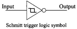
3. Schmitt Trigger
- Schmitt trigger is a device (or the input portion of a device) that has separate thresholds for a rising signal and a falling signal.
- It is a bistable circuit in which the output increases to a steady maximum when the input rises above a certain threshold and decreases almost to zero when the input voltage falls below another threshold.
- A comparator with hysteresis is also called a Schmitt trigger.
- The trigger points are found by applying the voltage-divider rule:
- Switching levels for the Schmitt Trigger are:

where UTP is Upper threshold point, and LTP is Lower threshold point.
- The Schmitt trigger is a comparator application which switches the output negative when the input passes upward through a positive reference voltage.
- It then uses positive feedback of a negative voltage to prevent switching back to the other state until the input passes through a lower threshold voltage, thus stabilizing the switching against rapid triggering by noise as it passes the trigger point.
- It provides feedback which is not reversed in phase, but in this case, the signal that is being fed back is a negative signal and keeps the output driven to the negative supply voltage until the input drops below the lower design threshold.
Applications of Schmitt Trigger: A Schmitt trigger is used in most applications where a level needs to be sensed. Even if only a small amount of hysteresis is used, it reduces the multiple transitions that can occur around.
- Digital to analogue conversion: The Schmitt trigger is effectively a one bit digital to analogue converter. When the signal reaches a given level it switches from its low to high state.
- Level detection: The Schmitt trigger circuit is able to provide level detection. When undertaking this application, it is necessary that the hysteresis voltage is taken into account so that the circuit switches on the required voltage.
- Line reception: When running a data line that may have picked up noise into a logic gate it is necessary to ensure that a logic output level is only changed as the data changed and not as a result of spurious noise that may have been picked up.
4. Sample and Hold Circuits
- Sample and hold circuits are used to sample an Analog signal and to store its value for some length of time.
- It is heavily used in data converters.
- Sample-and-hold circuits are also referred to as track-and-hold circuits.
- An equivalent circuit for the sample and hold is shown in the following figure.

- The switch connects the capacitor to the signal conditioning circuit once every sample period.
- The capacitor then holds the voltage value measured until a new sample is acquired.
- Many times, the sample and hold circuitry is incorporated into the same integrated circuit package.
Problems with a Sample and Hold:
- Finite Aperture Time: The sample and hold take a period of time to capture a sample of the sensor signal. This is called the aperture time. Since the signal will vary during this time, the sampled signal can be slightly off.
- Signal Feedthrough: When the sample and hold are not connected to the signal, the value being held should remain constant. Unfortunately, some signal does bleed through the switch to the capacitor, causing the voltage being held to change slightly.
- Signal Droop: The voltage is held on the capacitor starts to slowly decrease over time if the signal is not sampled often enough.
5. Active Filters
- An active filter means using amplifiers to improve the filter. An active filter generally uses an operational amplifier (op-amp) within its design.
- An electronic circuit that modifies the frequency spectrum of an arbitrary signal is called filter.
- A filter that modifies the spectrum producing amplification is said to be an active filter.
- Filtering components are resistance and capacitance only. Doesn’t include inductors
- Active components like op-amp, FET, transistors etc. are used
- It requires biasing voltage
- Its bandwidth is limited due to active component
- Gain is limited to the gain of active components used
- Small in size due to resistors and capacitors are used
- Due to active components like op-amp and FET input impedance is high
- Output impedance is low
- Basically used to suppress unwanted frequency components from information signals
- The main function of filters is to filter out required frequency components from mix frequency signal. They allow
- They allow a range of frequency to pass that is known as pass band and rejects (or suppresses) other frequencies known as stop band.
- The cut-off frequency is the parameter that separates out these two bands. So depending upon these pass band and stop band there are four types of filters: Low pass filters, High pass filters, Band pass filters, and Band reject filters.
- An advantage of active filters:
- They can provide gain
- They can provide isolation because of the typical characteristic impedances of amplifiers
- They can be cascaded because of the typical characteristic impedances of amplifiers
- They can avoid the use of inductors greatly simplifying the design of the filters.
- Disadvantages of active filters:
- They are limited by the amplifier’s bandwidth, and noise
- They need power supplies
- They dissipate more heat than a passive circuit.
6. Low pass filter (LPF)
- It allows to pass all the frequencies lower than its cut-off frequency and stops all other frequencies.
- A low-pass filter has a constant gain (=Vout/Vin) from 0 Hz to a high cut-off frequency fH.
- This cut off frequency is defined as the frequency where the voltage gain is reduced to 0.707, that is at fH the gain is down by 3 dB; after that (f > fH) it decreases as f increases.
- The frequencies between 0 Hz and fH are called pass band frequencies, whereas the frequencies beyond fH are the so-called stop band frequencies.
- A common use of a low-pass filter is to remove noise or other unwanted high-frequency components in a signal for which you are only interested in the dc or low-frequency components.
- Low-pass filters are also used to avoid aliasing in analog-digital conversion (which we will encounter in a few weeks). Correspondingly, a high-pass filter has a stop band for 0 < f < fL and where fL is the low cut off frequency.
- A simple, single-pole, low-pass filter (the integrator) is often used to stabilize amplifiers by rolling off the gain at higher frequencies where excessive phase shift may cause oscillations.
First Order Low Pass Filter Circuit:
- The transfer function of the circuit:
- Gain:
K=R2/R1
- Cutoff Frequency:
ωc=1/R2C
7. High pass filter (HPF)
- It allows to pass all the frequencies higher than its cut-off frequency and stops all other frequencies.
- A common use for a high-pass filter is to remove the dc component of a signal for which you are only interested in the ac components (such as an audio signal).
- A simple, single-pole, high-pass filter can be used to block dc offset in high gain amplifiers or single supply circuits.
- Filters can be used to separate signals, passing those of interest, and attenuating the unwanted frequencies.
First Order High Pass Filter Circuit:
- The transfer function of the circuit:

- Gain:
K=R2/R1
- Cutoff Frequency:
ωc=1/R1C
8. Band pass filter (BPF)
- It allows a passing band of frequencies between its higher cut-off and lower cut-off frequencies.
- If a high-pass filter and a low-pass filter are cascaded, a band pass filter is created.
- A bandpass filter has a pass band between two cut-off frequencies fH and fL, (fH > fL), and two stop bands 0 < f < fL and f > fH.
- The bandwidth of a bandpass filter is equal to fH -fL. Recall that we used a tunable bandpass filter to do harmonic spectrum analysis several weeks ago.
- The simplest band-pass filter can be made by combining the first order low pass and high pass filters.
- This circuit will attenuate low frequencies (w<<1/R2C2) and high frequencies (w>>1/R1C1) but will pass intermediate frequencies with a gain of -R1/R2. However, this circuit cannot be used to make a filter with a very narrow band.

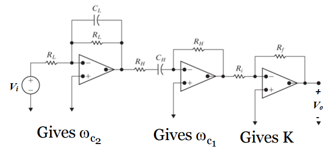
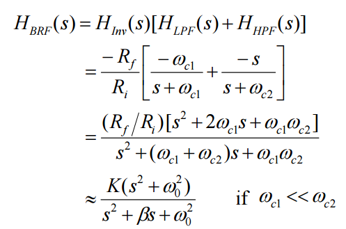
9. Band reject filter (BRF)
- It stops band of frequencies between its higher cut off and lower cut off frequencies.
- A complement to the band pass filter is the band-reject or notch filter.
- The pass bands include frequencies below fL and above fH. The band from fL to fH is in the stop band.
- First order Band Stop filter Circuit:
10. Scaling
- There are two ways of scaling a circuit: magnitude or impedance scaling, and frequency scaling.
- Both are useful in scaling responses and circuit elements to values within the practical ranges.
Magnitude Scaling:
- Magnitude scaling leaves the frequency response of a circuit unaltered.
- Magnitude scaling is the process of increasing all impedances in a network by a factor, the frequency response remaining unchanged.
Frequency Scaling:
- Frequency scaling shifts the frequency response up or down the frequency spectrum.
- Frequency scaling is the process of shifting the frequency response of a network up or down the frequency axis while leaving the impedance the same.
11. Passive Filter
- A passive filter is made up entirely of passive components such as resistors, capacitors and inductors.
- A low pass filter allows lower frequency signals to pass through but attenuates higher frequency signals.
The difference between Active and Passive Filters:
- Passive filters consume the energy of the signal, but no power gain is available; while active filters have a power gain.
- Active filters require an external power supply, while passive filters operate only on the signal input.
- Passive filters are constructed using only passive components (resistors, capacitors and inductors). Active filters may contain passive as well as active components.
- Active filters may contain passive as well as active components.
- Only passive filters use inductors. Active filters do not contain inductors.
- Only active filters use elements like op-amps and transistors, which are active elements.
- Theoretically, passive filters have no frequency limitations while active filters have limitations due to active elements.
- Passive filters can be used at high frequencies by using inductors.
- For Active filters, the frequency range is dependent on the bandwidth of the amplifier. Typically, to filter high-frequency signals, passive filters are used.
- Passive filters have a better stability and can withstand large currents.
- Passive filters are relatively cheaper than active filters.
All the Best.
Team Gradeup!


